Ipv4
An IPv4 packet has two parts:
- IP Header – Identifies the packet characteristics.
- Payload – Contains the Layer 4 segment information and the actual data.
As shown in the figure, an IPv4 packet header consists of fields containing important information about the packet. These fields contain binary numbers which are examined by the Layer 3 process. The binary values of each field identify various settings of the IP packet.
Significant fields
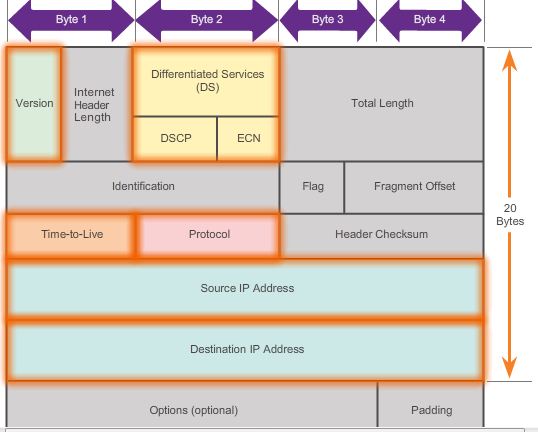
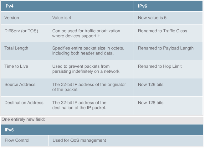
- Version – Contains a 4-bit binary value identifying the IP packet version. For IPv4 packets, this field is always set to 0100.
- Differentiated Services (DS) – Formerly called the Type of Service (ToS) field, the DS field is an 8-bit field used to determine the priority of each packet.
- The first 6 bits identify the Differentiated Services Code Point (DSCP) value that is used by a quality of service (QoS) mechanism. The
- Last 2 bits identify the Explicit Congestion notification (ECN) value that can be used to prevent dropped packets during times of network congestion.
- Time-to-Live (TTL) – Contains an 8-bit binary value that is used to limit the lifetime of a packet. It is specified in seconds but is commonly referred to as hop count. The packet sender sets the initial time-to-live (TTL) value and is decreased by one each time the packet is processed by a router, or hop. If the TTL field decrements to zero, the router discards the packet and sends an Internet Control Message Protocol (ICMP) Time Exceeded message to the source IP address. The traceroute command uses this field to identify the routers used between the source and destination.
- Protocol – This 8-bit binary value indicates the data payload type that the packet is carrying, which enables the network layer to pass the data to the appropriate upper-layer protocol. Common values include ICMP (1), TCP (6), and UDP (17).
- Source IP Address – Contains a 32-bit binary value that represents the source IP address of the packet.
- Destination IP Address – Contains a 32-bit binary value that represents the destination IP address of the packet.
Other fields
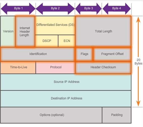 The fields used to identify and validate the packet include:
- Internet Header Length (IHL) – Contains a 4-bit binary value identifying the number of 32-bit words in the header. The IHL value varies due to the Options and Padding fields. The minimum value for this field is 5 (i.e., 5×32 = 160 bits = 20 bytes) and the maximum value is 15 (i.e., 15×32 = 480 bits = 60 bytes).
- Total Length – Sometimes referred to as the Packet Length, this 16-bit field defines the entire packet (fragment) size, including header and data, in bytes. The minimum length packet is 20 bytes (20-byte header + 0 bytes data) and the maximum is 65,535 bytes.
- Header Checksum – The 16-bit field is used for error checking of the IP header. The checksum of the header is recalculated and compared to the value in the checksum field. If the values do not match, the packet is discarded.
A router may have to fragment a packet when forwarding it from one medium to another medium that has a smaller MTU. When this happens, fragmentation occurs and the IPv4 packet uses the following fields to keep track of the fragments:
- Identification – This 16-bit field uniquely identifies the fragment of an original IP packet.
- Flags – This 3-bit field identifies how the packet is fragmented. It is used with the Fragment Offset and Identification fields to help reconstruct the fragment into the original packet.
- Fragment Offset – This 13-bit field identifies the order in which to place the packet fragment in the reconstruction of the original unfragmented packet.
IPv4 classes
| Class | 1st Octet Decimal Range | 1st Octet High Order Bits | Network/Host ID (N=Network, H=Host) | Default Subnet Mask | Number of Networks | Hosts per Network (Usable Addresses) |
|---|---|---|---|---|---|---|
| A | 1 – 126* | 0 | N.H.H.H | 255.0.0.0 | 126 (27 – 2) | 16,777,214 (224 – 2) |
| B | 128 – 191 | 10 | N.N.H.H | 255.255.0.0 | 16,382 (214 – 2) | 65,534 (216 – 2) |
| C | 192 – 223 | 110 | N.N.N.H | 255.255.255.0 | 2,097,150 (221 – 2) | 254 (28 – 2) |
| D | 224 – 239 | 1110 | Reserved for Multicasting | |||
| E | 240 – 254 | 1111 | Experimental; used for research | |||
Note: Class A addresses 127.0.0.0 to 127.255.255.255 cannot be used and is reserved for loopback and diagnostic functions.
Private IP Addresses
| Class | Private Networks | Subnet Mask | Address Range |
|---|---|---|---|
| A | 10.0.0.0 | 255.0.0.0 | 10.0.0.0 – 10.255.255.255 |
| B | 172.16.0.0 – 172.31.0.0 | 255.240.0.0 | 172.16.0.0 – 172.31.255.255 |
| C | 192.168.0.0 | 255.255.0.0 | 192.168.0.0 – 192.168.255.255 |
Pages: 1 2