EIGRP operation
1. Neighbor Adjacency
EIGRP uses Hello packets to establish and maintain neighbor adjacencies. For two EIGRP routers to become neighbors, several parameters between the two routers must match. For example, two EIGRP routers must use the same EIGRP metric parameters and both must be configured using the same autonomous system number.
2. Topology table
EIGRP updates contain networks that are reachable from the router sending the update. As EIGRP updates are exchanged between neighbors, the receiving router adds these entries to its EIGRP topology table.
Each EIGRP router maintains a topology table for each routed protocol configured, such as IPv4 and IPv6. The topology table includes route entries for every destination that the router learns from its directly connected EIGRP neighbors. When a router receives an EIGRP routing update, it adds the routing information to its EIGRP topology table and replies with an EIGRP acknowledgment.
3. Convergence
After receiving the EIGRP update packets from neighbor, using the information in the topology table, the receiving router updates its IP routing table with the best path to each destination, including the metric and the next-hop router.
Other router updates its IP routing table with the best path routes to each network.
4. Route States
A topology table entry for a destination can have one of two states. A route is considered in the Passive state when a router is not performing a route recomputation. The route is in Active state when a router is undergoing a route recomputation. If there are always feasible successors, a route never has to go into Active state and avoids a route recomputation.
When there are no feasible successors, a route goes into Active state and a route recomputation occurs. A route recomputation commences with a router sending a query packet to all neighbors. Neighboring routers can either reply if they have feasible successors for the destination or optionally return a query indicating that they are performing a route recomputation. While in Active state, a router cannot change the next-hop neighbor it is using to forward packets. Once all replies are received for a given query, the destination can transition to Passive state and a new successor can be selected.
When a link to a neighbor that is the only feasible successor goes down, all routes through that neighbor commence a route recomputation and enter the Active state.
Metrics
Metric Weights
By default, EIGRP uses the following values in its composite metric to calculate the preferred path to a network:
- Bandwidth – The slowest bandwidth among all of the outgoing interfaces, along the path from source to destination.
- Delay – The cumulative (sum) of all interface delay along the path (in tens of microseconds).
The following values can be used, but are not recommended, because they typically result in frequent recalculation of the topology table:
- Reliability – Represents the worst reliability between the source and destination, which is based on keepalives.
- Load – Represents the worst load on a link between the source and destination, which is computed based on the packet rate and the configured bandwidth of the interface.
Note: Although the MTU is included in the routing table updates, it is not a routing metric used by EIGRP.
Composite Metric
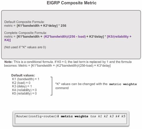
The formula consists of values K1 to K5, known as EIGRP metric weights. K1 and K3 represent bandwidth and delay, respectively. K2 represents load, and K4 and K5 represent reliability. By default, K1 and K3 are set to 1, and K2, K4, and K5 are set to 0. The result is that only the bandwidth and delay values are used in the computation of the default composite metric. EIGRP for IPv4 and EIGRP for IPv6 use the same formula for the composite metric.
The metric calculation method (k values) and the EIGRP autonomous system number must match between EIGRP neighbors. If they do not match, the routers do not form an adjacency.
The default k values can be changed with the metric weights router configuration mode command:
Router(config-router)# metric weights tos k1 k2 k3 k4 k5
Note: Modifying the metric weights value is generally not recommended
Verifying the k Values
The show ip protocols command is used to verify the k values
Examining the Metric Values
The show interfaces command displays interface information, including the parameters used to compute the EIGRP metric.
- BW – Bandwidth of the interface (in kilobits per second).
- DLY – Delay of the interface (in microseconds).
- Reliability – Reliability of the interface as a fraction of 255 (255/255 is 100% reliability), calculated as an exponential average over five minutes. By default, EIGRP does not include its value in computing its metric.
- Txload, Rxload – Transmit and receive load on the interface as a fraction of 255 (255/255 is completely saturated), calculated as an exponential average over five minutes. By default, EIGRP does not include its value in computing its metric.
Note: In cisco tutorial bandwidth is referenced as kb/s. However, router output displays bandwidth using the Kbit/sec abbreviation. Router output also displays delay as usec. In this course, delay is referenced as microseconds.
Bandwidth Metric
The bandwidth metric is a static value used by some routing protocols, such as EIGRP and OSPF, to calculate their routing metric. The bandwidth is displayed in kilobits per second (kb/s). Most serial interfaces use the default bandwidth value of 1544 kb/s or 1,544,000 b/s (1.544 Mb/s). This is the bandwidth of a T1 connection.
The default value of the bandwidth may or may not reflect the actual physical bandwidth of the interface. If actual bandwidth of the link differs from the default bandwidth value, the bandwidth value should be modified.
Router(config-if)# bandwidth kilobits-bandwidth-value
Use the no bandwidth command to restore the default value.
Delay Metric
Delay is the measure of the time it takes for a packet to traverse a route.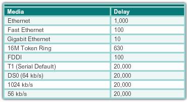
The delay (DLY) metric is a static value based on the type of link to which the interface is connected and is expressed in microseconds. When used to determine the EIGRP metric, delay is the cumulative (sum) of all interface delays along the path.
Calculate the Metric
Step 1. Determine the link with the slowest bandwidth. Use that value to calculate bandwidth (10,000,000/bandwidth).
Step 2. Determine the delay value for each outgoing interface on the way to the destination. Add the delay values and divide by 10 (sum of delay/10).
Step 3. Add the computed values for bandwidth and delay, and multiply the sum by 256 to obtain the EIGRP metric.
DUAL ( Diffusing Update Algorithm)
The DUAL algorithm is used to obtain loop-freedom at every instance throughout a route computation. This allows all routers involved in a topology change to synchronize at the same time. Routers that are not affected by the topology changes are not involved in the recomputation. This method provides EIGRP with faster convergence times than other distance vector routing protocols.
- The decision process for all route computations is done by the DUAL Finite State Machine (FSM). An FSM is a workflow model, similar to a flow chart that is composed of the following:
- A finite number of stages (states)
- Transitions between those stages
- Operations
The DUAL FSM tracks all routes, uses EIGRP metrics to select efficient, loop-free paths, and identify the routes with the least-cost path to be inserted into the routing table.
Recomputation of the DUAL algorithm can be processor-intensive. EIGRP avoids recomputation whenever possible by maintaining a list of backup routes that DUAL has already determined to be loop-free. If the primary route in the routing table fails, the best backup route is immediately added to the routing table.
Active route:
- A successor (Router which is forwarding via best path) is a neighboring router that is used for packet forwarding and has the least-cost route to the destination network. The IP address of a successor is shown in a routing table entry right after the word via.
- FD(FEASIBLE DISTANCE) (best metric) is the lowest calculated metric to reach the destination network. FD is the metric listed in the routing table entry as the second number inside the brackets. As with other routing protocols, this is also known as the metric for the route.
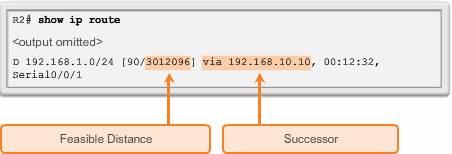
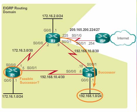
Notice that EIGRP’s best path for the 192.168.1.0/24 network is through router R3, and that the feasible distance is 3,012,096.
Backup route:
- FC( feasibility condition):
The feasibility condition is a sufficient condition for loop freedom in EIGRP-routed network. It is used to select the successors and feasible successors that are guaranteed to be on a loop-free route to a destination. The FC is met when a neighbor’s Reported Distance (RD) to a network is less than the local router’s feasible distance to the same destination network, which means the neighbor is on the same path that the local router is using to the destination, not another path. For more info check here. - R2 uses this information to determine if R1 meets the FC and, therefore, can be an FS.RD( reported distance): Reported distance is the total metric along a path to a destination network as advertised by an upstream neighbor. If the reported distance is less, it represents a loop-free path. The reported distance is simply an EIGRP neighbor’s feasible distance to the same destination network. The reported distance is the metric that a router reports to a neighbor about its own cost to that network.
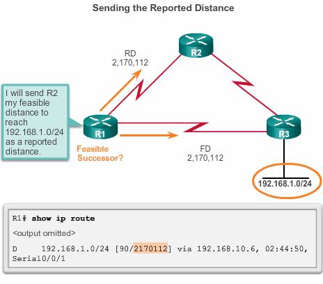 In the Figure, R1’s feasible distance to 192.168.1.0/24 is 2,170,112.R1 reports to R2 that its FD to 192.168.1.0/24 is 2,170,112.From R2’s perspective, 2,170,112 is R1’s RD.
 - FS:
DUAL can converge quickly after a change in the topology because it can use backup paths to other networks without recomputing DUAL. These backup paths are known as Feasible Successors (FSs). A feasible successor is a path whose reported distance is less than the feasible distance( so we use the neighbor’s path, not the feasible successor’s .
An FS is a neighbor that has a loop-free backup path to the same network as the successor, and it satisfies the Feasibility Condition (FC). R2’s successor for the 192.168.1.0/24 network is R3, providing the best path or lowest metric to the destination network.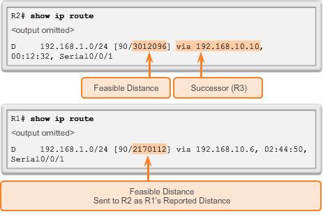 Because the RD of R1 (2,170,112) is less than R2’s own FD (3,012,096), R1 meets the FC.R1 is now an FS for R2 to the 192.168.1.0/24 network.If there is a failure in R2’s path to 192.168.1.0/24 via R3 (successor), then R2 immediately installs the path via R1 (FS) in its routing table. R1 becomes the new successor for R2’s path to this network
Example:
How Loop free network achieved
Consider the following topology.
R1 is our router which has a route to R5. Suppose the path through R2 is better (the lowest FD), so R2 is becoming our Successor for that route. Now R1 has to decide if R3 will become a Feasible Successor or not. Let’s split this into 2 cases.
1) Suppose R1’s distance to R5 (which is FD) is 100, whereas R3’s distance to R5 through R4 is 120 (which is RD). Let’s violate the feasibility condition and choose R3 as a Feasible Successor.
What happens when we configure unequal load balancing? R1 sends some IP packets to R5 through R3. When a packet comes to the next hop, R3 thinks “I need to send it towards R5, so let’s consult my routing table”. And guess what? The routing table will tell R3 to send the packet back to R1 because R1 is the Successor for that route, in R3’s point of view (remember that distance on the left is 100+X, and 120 on the right; X is distance between R1 and R3 which may easily be less than 20). So we have a loop, as the packet can bounce between R1 and R3 never going to other routers.
2) Suppose R1’s distance to R5 (which is FD) is 100, whereas R3’s distance to R5 through R4 is 95 (which is RD). Now whatever distance X is between R1 and R3, 100+X always greater than 95, so R3 will never route through R1. This is why it’s a loop free path.

Topology Table
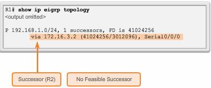
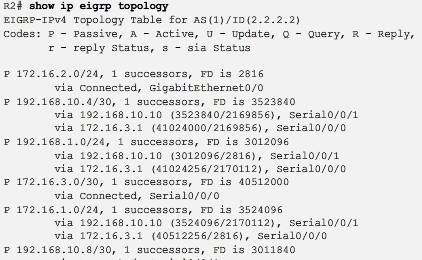
Show ip eigrp topology
On router 2use the show ip eigrp topology command to view the topology table. The topology table lists all successors and FSs that DUAL has calculated to destination networks. Only the successor is installed into the IP routing table.
Let’s take a look at one Entry
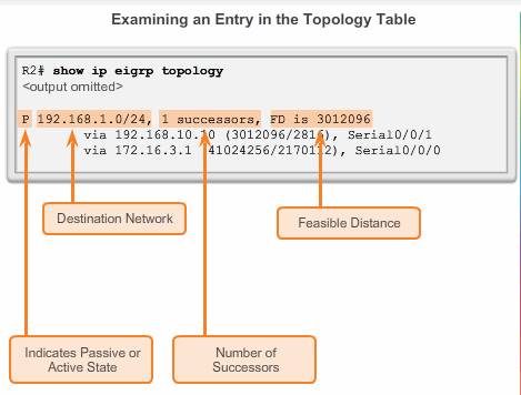
- P – Route in the passive state.
When DUAL is not performing its diffusing computations to determine a path for a network, the route is in a stable mode, known as the passive state. If DUAL recalculates or searches for a new path, the route is in an active state and displays an A. All routes in the topology table should be in the passive state for a stable routing domain.
- 192.168.1.0/24 – Destination network that is also found in the routing table.
- 1 successors – Displays the number of successors for this network. If there are multiple equal cost paths to this network, there are multiple successors.
- FD is 3012096 – FD, the EIGRP metric to reach the destination network. This is the metric displayed in the IP routing table.
- via 192.168.10.10 – Next-hop address of the successor, R3. This address is shown in the routing table.
- 3012096 – FD to 192.168.1.0/24. It is the metric shown in the IP routing table.
- 2816 – RD of the successor and is R3’s cost to reach this network.
- Serial 0/0/1 – Outbound interface used to reach this network, also shown in the routing table.
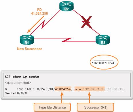
- via 172.16.3.1 – Next-hop address of the FS, R1.
- 41024256 – R2’s new FD to 192.168.1.0/24, if R1 became the new successor and would be the new metric displayed in the IP routing table.
- 2170112 – RD of the FS, or R1’s metric to reach this network. RD must be less than the current FD of 3,012,096 to meet the FC.
- Serial 0/0/0 – This is the outbound interface used to reach FS, if this router becomes the successor.
No feasible successor
To see how DUAL uses successors and FSs, examine the routing table of R1, assuming the network is converged.
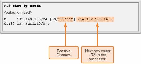
Figure above displays a partial output from the show ip route command on R1. The route to 192.168.1.0/24 shows that the successor is R3 via 192.168.10.6 with an FD of 2,170,112.
The IP routing table only includes the best path, the successor. To see if there are any FSs, we must examine the EIGRP topology table.
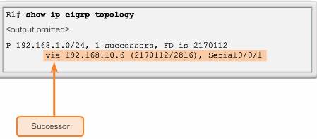
The topology table only shows the successor 192.168.10.6, which is R3. There are no FSs. By looking at the actual physical topology or network diagram, it is obvious that there is a backup route to 192.168.1.0/24 through R2. R2 is not an FS because it does not meet the FC. Although, looking at the topology, it is obvious that R2 is a backup route, EIGRP does not have a map of the network topology. EIGRP is a distance vector routing protocol and only knows about remote network information through its neighbors.
DUAL does not store the route through R2 in the topology table. All links can be displayed using the show ip eigrp topology all-links command. This command displays links whether they satisfy the FC or not.
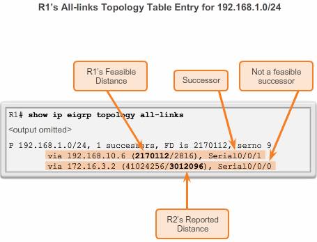
The show ip eigrp topology all-links command shows all possible paths to a network, including successors, FSs, and even those routes that are not FSs. R1’s FD to 192.168.1.0/24 is 2,170,112 via the successor R3. For R2 to be considered a FS, it must meet the FC. R2’s RD to R1 to reach 192.168.1.0/24 must be less the R1’s current FD. Per the figure, R2’s RD is 3,012,096, which is higher than R1’s current FD of 2,170,112.
Even though R2 looks like a viable backup path to 192.168.1.0/24, R1 has no idea that the path is not a potential loop back through itself. EIGRP is a distance vector routing protocol, without the ability to see a complete, loop-free topological map of the network. DUAL’s method of guaranteeing that a neighbor has a loop-free path is that the neighbor’s metric must satisfy the FC. By ensuring that the RD of the neighbor is less than its own FD, the router can assume that this neighboring router is not part of its own advertised route; thus, always avoiding the potential for a loop.
R2 can be used as a successor if R3 fails; however, there is a longer delay before adding it to the routing table. Before R2 can be used as a successor, DUAL must do further processing.
DUAL and convergence
The centerpiece of EIGRP is DUAL and its EIGRP route-calculation engine. The actual name of this technology is DUAL Finite State Machine (FSM). This FSM contains all of the logic used to calculate and compare routes in an EIGRP network. The figure shows a simplified version of the DUAL FSM.
An FSM is an abstract machine, not a mechanical device with moving parts. FSMs define a set of possible states that something can go through, what events cause those states, and what events result from those states. Designers use FSMs to describe how a device, computer program, or routing algorithm reacts to a set of input events.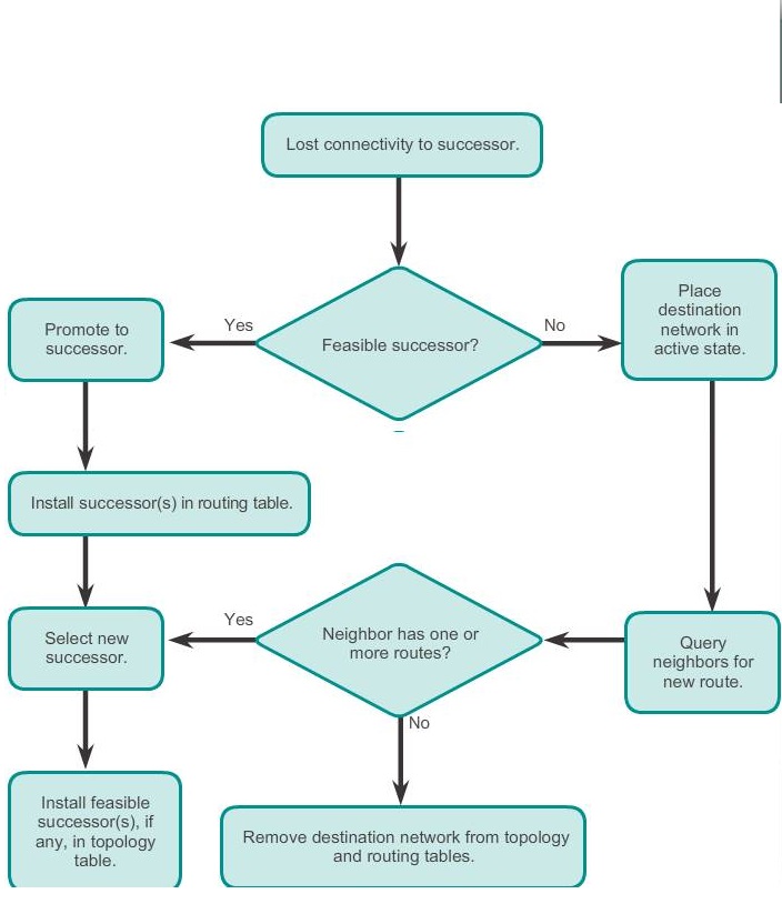
FSMs are beyond the CCNA. However, the concept is used to examine some of the output from EIGRP’s FSM using the debug eigrp fsm command. Use this command to examine what DUAL does when a route is removed from the routing table.
Occasionally, the path to the successor fails and there are not any FSs. In this instance, DUAL does not have a guaranteed loop-free backup path to the network, so the path is not in the topology table as an FS. If there are not any FSs in the topology table, DUAL puts the network into the active state. DUAL actively queries its neighbors for a new successor.
R1 is currently using R3 as the successor to 192.168.1.0/24, as shown in topology. However, R1 does not have R2 listed as an FS, because R2 does not satisfy the FC. To understand how DUAL searches for a new successor when there is no FS, a link failure is simulated between R1 and R3.
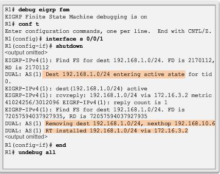
Before the link failure is simulated, DUAL debugging is enabled with the debug eigrp fsm command on R1, as shown in Figure below. A link failure is simulated using the shutdown command on the Serial 0/0/1 interface on R1.
When the successor is no longer available and there is no feasible successor, DUAL puts the route into an active state. DUAL sends EIGRP queries asking other routers for a path to the network. Other routers return EIGRP replies, letting the sender know whether or not they have a path to the requested network. If none of the EIGRP replies have a path to this network, the sender of the query does not have a route to this network.
The selected debug output in Figure above shows the 192.168.1.0/24 network put into the active state and EIGRP queries sent to other neighbors. R2 replies with a path to this network, which becomes the new successor and is installed into the routing table.
If the sender of the EIGRP queries receives EIGRP replies that include a path to the requested network, the preferred path is added as the new successor and added to the routing table. This process takes longer than if DUAL had an FS in its topology table and was able to quickly add the new route to the routing table. In Figure below, notice that R1 has a new route to the 192.168.1.0/24 network. The new EIGRP successor is router R2.
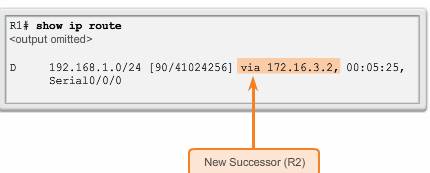
Figure below shows that the topology table for R1 now has R2 as the successor with no new FSs. If the link between R1 and R3 is made active again, R3 returns as the successor. However, R2 is still not the FS, because it does not meet the FC.