BPDU process
The BPDU message is encapsulated in an Ethernet frame when it is transmitted across the network. The 802.3 header indicates the source and destination addresses of the BPDU frame. This frame has a destination MAC address of 01:80:C2:00:00:00, which is a multicast address for the spanning tree group. When a frame is addressed with this MAC address, each switch that is configured for spanning tree accepts and reads the information from the frame; all other devices on the network disregard the frame.
Each switch in the broadcast domain initially assumes that it is the root bridge for a spanning tree instance, so the BPDU frames sent contain the BID of the local switch as the root ID. Each switch maintains local information about its own BID, the root ID, and the path cost to the root.
When adjacent switches receive a BPDU frame, they compare the root ID from the BPDU frame with the local root ID.
- If the root ID in the BPDU is lower than the local root ID, the switch updates the local root ID and the ID in its BPDU messages. These messages indicate the new root bridge on the network. The distance to the root bridge is also indicated by the path cost update.
- If the local root ID is lower than the root ID received in the BPDU frame, the BPDU frame is discarded.
After a root ID has been updated to identify a new root bridge, all subsequent BPDU frames sent from that switch contain the new root ID and updated path cost.
Varieties of Spanning tree protocols
The varieties of spanning tree protocols include:
- STP – This is the original IEEE 802.1D version (802.1D-1998 and earlier) that provides a loop-free topology in a network with redundant links. Common Spanning Tree (CST) assumes one spanning tree instance for the entire bridged network, regardless of the number of VLANs.
Because there is only one instance, there is only one root bridge and one tree. Traffic for all VLANs flows over the same path, which can lead to suboptimal traffic flows.
- PVST+ – This is a Cisco enhancement of STP that provides a separate 802.1D spanning tree instance for each VLAN configured in the network. The separate instance supports PortFast, UplinkFast, BackboneFast, BPDU guard, BPDU filter, root guard, and loop guard.
Creating an instance for each VLAN increases the CPU and memory requirements, but allows for per-VLAN root bridges. This design allows the spanning tree to be optimized for the traffic of each VLAN. Convergence of this version is similar to the convergence of 802.1D. However, convergence is per-VLAN.
- 802.1D-2004 – This is an updated version of the STP standard, incorporating IEEE 802.1w.
- Rapid Spanning Tree Protocol (RSTP) or IEEE 802.1w – This is an evolution of STP that provides faster convergence than STP.
It still provides a single instance of STP, it does not address the suboptimal traffic flow issues.
- Rapid PVST+ – This is a Cisco enhancement of RSTP that uses PVST+. Rapid PVST+ provides a separate instance of 802.1w per VLAN. The separate instance supports PortFast, BPDU guard, BPDU filter, root guard, and loop guard.
This version addresses both the convergence issues and the suboptimal traffic flow issues. However, this version has the largest CPU and memory requirements.
- Multiple Spanning Tree Protocol (MSTP) – This is an IEEE standard inspired by the earlier Cisco proprietary Multiple Instance STP (MISTP) implementation. MSTP maps multiple VLANs into the same spanning tree instance. The Cisco implementation of MSTP is MST, which provides up to 16 instances of RSTP and combines many VLANs with the same physical and logical topology into a common RSTP instance. Each instance supports PortFast, BPDU guard, BPDU filter, root guard, and loop guard.
- MST – The Cisco implementation of MSTP, which provides up to 16 instances of RSTP (802.1w) and combines many VLANs with the same physical and logical topology into a common RSTP instance. Each instance supports PortFast, BPDU guard, BPDU filter, root guard, and loop guard. The CPU and memory requirements of this version are less than those of Rapid PVST+, but more than those of RSTP.The default spanning tree mode for Cisco Catalyst switches is PVST+, which is enabled on all ports. PVST+ has much slower convergence after a topology change than Rapid PVST+.
Note that IEEE 802.1D-2004 incorporates RSTP functionality, while IEEE 802.1D-1998 refers to the original implementation of the spanning tree algorithm.
The characteristics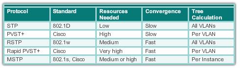
Port states
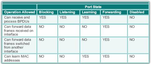
- Blocking – The port is an alternate port and does not participate in frame forwarding. The port only receives BPDU frames to determine the location and root ID of the root bridge switch and what port roles each switch port should assume in the final active STP topology.
- Listening – Listens for the path to the root. STP has determined that the port can participate in frame forwarding according to the BPDU frames that the switch has received thus far. At this point, the switch port not only receives BPDU frames, it also transmits its own BPDU frames and inform adjacent switches that the switch port is preparing to participate in the active topology.
- Learning – Learns the MAC addresses. The port prepares to participate in frame forwarding and begins to populate the MAC address table.
- Forwarding – The port is considered part of the active topology. It forwards data frames and sends and receives BPDU frames.
- Disabled – The Layer 2 port does not participate in spanning tree and does not forward frames. The disabled state is set when the switch port is administratively disabled
BPDU Guard, which is a feature that shuts down a PortFast-enabled port in the event a BPDU is received.
Command
Manual configure port cost: S1(conf-if)#spanning-tree cost value
Method 1
To ensure that the switch has the lowest bridge priority value, use the
S1(config)# spanning-tree vlan vlan-id root primaryIf an alternate root bridge is desired, use the
s1(config)#spanning-tree vlan vlan-id root secondary global configuration mode
Or
Method 2
Another method for configuring the bridge priority value is using the
spanning-tree vlan vlan-id priority valueglobal configuration mode command.This command gives more granular control over the bridge priority value. The priority value is configured in increments of 4,096 between 0 and 61,440.
- Show mac-address-table: show the mac address – interface mapping table
- verify the port and path cost to the root bridge, enter the
show spanning-tree
If the current switch is the root bridge, a text “We are the root of the spanning tree” will appear in the fourth line.
- Display the ports states:
show spanning-tree summary - display spanning tree info for active interface only:
show spanning-tree active - Show specific vlan:
show spanning-tree vlan vlan_number - Debug STP:
S1#debug spanning-tree events
IEEE 802.1D Path Cost Parameter Values
| Link Speed | Recommended Value |
Recommended Range |
Range |
|---|---|---|---|
| 4 Mbps | 250 | 100-1000 | 1-65535 |
| 10 Mbps | 100 | 50-600 | 1-65535 |
| 16 Mbps | 62 | 40-400 | 1-65535 |
| 100 Mbps | 19 | 10-60 | 1-65535 |
| 1 Gbps | 4 | 3-10 | 1-65535 |
| 10 Gbps | 2 | 1-5 | 1-65535 |
IEEE 802.1t Path Cost Parameter Values
| Link Speed | Recommended Value |
Recommended Range |
Range |
|---|---|---|---|
| 10 Mbps | 2.000.000 | 200.000-20.000.000 | 1-200.000.000 |
| 100 Mbps | 200.000 | 20.000-2.000.000 | 1-200.000.000 |
| 1 Gbps | 20.000 | 2.000-200.000 | 1-200.000.000 |
| 10 Gbps | 2.000 | 200-20.000 | 1-200.000.000 |
| 100 Gbps | 200 | 20-2.000 | 1-200.000.000 |
| 1 Tbps | 20 | 2-200 | 1-200.000.000 |
| 10 Tbps | 2 | 1-20 | 1-200.000.000 |
Default Observed on Cisco Switches
| Speed | Port Cost | Comment |
|---|---|---|
| 10 Mbps | 100 | Ethernet |
| 20 Mbps | 56 | EtherChannel |
| 30 Mbps | 47 | EtherChannel |
| 40 Mbps | 41 | EtherChannel |
| 50 Mbps | 35 | EtherChannel |
| 54 Mbps | 33 | 802.11 wireless |
| 60 Mbps | 30 | EtherChannel |
| 70 Mbps | 26 | EtherChannel |
| 80 Mbps | 23 | EtherChannel |
| 100 Mbps | 19 | Fast Ethernet |
| 200 Mbps | 12 | Fast EtherChannel |
| 300 Mbps | 9 | Fast EtherChannel |
| 400 Mbps | 8 | Fast EtherChannel |
| 500 Mbps | 7 | Fast EtherChannel |
| 600 Mbps | 6 | Fast EtherChannel |
| 700 Mbps | 5 | Fast EtherChannel |
| 800 Mbps | 5 | Fast EtherChannel |
| 1 Gbps | 4 | Gigabit Ethernet |
| 2 Gbps | 3 | Gigabit EtherChannel |
| 10 Gbps | 2 | 10G Ethernet |
| 20 Gbps | 1 | 20G EtherChannel |
| 40 Gbps | 1 | 40G EtherChannel |
6 Common Spanning tree problems
Not configuring spanning tree at all
Spanning tree is a good thing. But for some reason, a lot of switch vendors disable it by default. So out of the box, you might have to enable the protocol.
Sometimes people deliberately disable spanning tree. The most common reason for disabling spanning tree is that the original 802.1D Spanning Tree Protocol (STP) goes through a fairly lengthy wait period from the time a port becomes electrically active to when it starts to pass traffic. This wait period, typically 45 seconds, is long enough that DHCP can give up trying to get an IP address for this new device.
One solution to the problem is to simply disable spanning tree on the switch. This is the wrong solution.
The right solution is to configure a feature called PortFast on Cisco switches. (Most switch vendors have a similar feature.) You configure the command “spanning-tree portfast” on all the ports connecting to end devices like workstations. They then automatically bypass the wait period and DHCP works properly.
It’s important to only configure this command on ports that connect to end devices though. Ports connecting to other switches need to exchange spanning tree information.
Letting the network pick your root bridge
As the name suggests, spanning tree resolves loops in your network by creating a logical tree structure between the switches. One switch becomes the root of the tree, and is called the root bridge. All other switches then figure out the best path to get to the root bridge.
If there are multiple paths, then on each switch, spanning tree selects the best path and puts all the other ports into a blocking state. In this way, there’s a single path between any two devices on the network, although it might be rather circuitous.
Every switch taking part in spanning tree has a bridge priority. The switch with the lowest priority becomes the root bridge. If there’s a tie, then the switch with the lowest bridge ID number wins. The ID number is typically derived from a MAC address on the switch.
The problem is that, by default, every switch has the same priority value (32768). So if you don’t manually configure a better (lower) bridge priority value on a particular switch, the network will simply select a root for you. Then Murphy’s Law applies. The resulting root bridge could be some tiny edge switch with slow uplinks and limited backplane resources.
To make matters worse, a bad choice of root bridge can make the network less stable. If there’s a connectivity problem that takes any random switch off the network, spanning tree heals rather quickly. But if the root bridge goes down, or if the failure means that some switches no longer have a path to the root bridge, this constitutes a major topology change. A new root bridge needs to be selected. The entire network will freeze during this time and no packets can be forwarded.
I always recommend making the core switch the root bridge. I also like to select a backup root bridge. If there are dual redundant core switches, then one is the root bridge and the other becomes my backup.
Set the bridge priority on the primary root bridge to the best possible value—4096—and the backup root bridge to the next best value—8192. Why these funny numbers? Well, that’s a longer story that we don’t have space for here, but the lower order bits in the priority field have another purpose, so they aren’t available for use as priorities.
Using legacy 802.1D
The first open standard for spanning tree is called 802.1D. It’s one of the earliest standards in the IEEE 802 series of standards that includes the specifications for every type of Ethernet and Wi-Fi as well as a bunch of other protocols. It works well despite its age, and you’ll find this type of spanning tree on just about every switch. Any switch that doesn’t support 802.1D is only useful in small isolated environments, and should never be connected to any other switches.
But there have been several important advancements to spanning tree since 802.1D. These
improvements allow sub-second convergence following a link failure, as well as the ability to scale to larger networks and the ability to actually have different spanning tree topologies and different root bridges for different VLANs. So it makes a whole lot of sense to use them.
Most modern Cisco switches default to a protocol called Per-VLAN RSTP. This stands for Rapid Spanning Tree Protocol. It automatically operates a separate spanning tree domain with a separate root bridge on every VLAN. In practice, it’s common to make the same switch the root bridge on all or most of the VLANs, though.
The rapid feature or RSTP is what you’ll probably find most useful. This allows the network to recover from most failures in times on the order of 1 to 2 seconds. Multiple Instance Spanning Tree, or MST, is similar to RSTP. The main difference is that you can designate groups of VLANs that are all part of the same tree structure with a single common root bridge. However, I recommend using Per-VLAN RSTP in most cases because it’s easier to configure. Also, I’ve encountered some interoperabilty problems with MSTP between different switch vendors.
Mixing spanning tree types
It should be pretty clear from the descriptions of 802.1D, RSTP, and MST in the previous section that mixing them could get messy. The RSTP and MST protocols have rules for how to deal with this mixing, and in general it involves creating separate zones within the network for groups of switches running different flavours of spanning tree. This rarely results in the most efficient paths being selected between devices.
The only really valid reason to mix spanning tree types is to allow the inclusion of legacy
equipment that doesn’t support the more modern protocols. As time goes by, there should be fewer and fewer of these legacy devices, and the number of places where it makes sense to mix the protocols should becomes smaller.
I recommend picking one, preferably RSTP or MST, and just using that in a consistent manner across all of your switches.
Using MST with pruned trunks
Because MST allows a single spanning tree structure that supports multiple VLANs, you need to be extremely careful about your inter-switch trunks.
I once had a client with a large complicated network involving many switches and many VLANs. They were running MST. For simplicity, they had designated a single MST instance, meaning that all VLANs were controlled by the same root bridge.
The problem for this client arose when they decided that certain VLANs should only exist on certain switches for security reasons. All perfectly reasonable. So they removed the VLAN from the main inter-switch trunks, and added new special trunks just for these secure VLANs. And everything broke.
MST considered all VLANs to be part of the same tree, and it selected which trunks to block and which to forward based on that assumption. But in this case, because some VLANs were only present on some trunks and other VLANs were present on the other trunks, blocking a trunk meant only passing some of the VLANs. Blocking the other trunk meant only passing the other set of VLANs. For the blocked VLANs there was simply no path to the root bridge at all.
So, if you’re going to use MST, you need to either ensure that all VLANs are passed on all trunks, or you need to carefully and manually create different MST instances for each group of VLANs with special topological requirements. In other words, you have to do careful analysis and design the network properly. Or you could take the easy way out and run Per-VLAN RSTP.
Conflicting root bridge and HSRP/VRRP
Another common topological problem with spanning tree networks involves the way that Layer 2 and 3 redundancy mechanisms sometimes interact.
Suppose I have a network core consisting of two Layer 3 switches. On each segment I want these core switches to act as redundant default gateways. And I want to connect all of the downstream switches redundantly to both core switches and make spanning tree remove the loops.
In this scenario, the spanning tree root bridge for a particular VLAN might be on one of these core switches and HSRP/VRRP master default gateway on the other switch. Then an Ethernet frame originating on one of the downstream switches destined to the default gateway will need to take an extra hop, going first to the root bridge, and then to the secondary core switch that currently owns the default gateway IP.
Normally this isn’t a problem, but imagine that I’m passing packets between two VLANs, both with Core Switch A as the root bridge and Core Switch B as the default gateway. Every packet must go up to Core Switch A, and cross the backbone link to get routed on Core Switch B.
Then it has to cross the backbone link again to go back to Core Switch A to be delivered to its destination. All of the return packets must also cross the backbone link twice. This creates a massive traffic burden on the backbone link where every packet in both directions must cross twice. It also incurs a latency penalty as every packet needs to be serialized and transmitted twice. Even on 10Gbps links, this will typically cost a couple of microseconds in both directions, which could add up for particularly sensitive applications.
Suppose instead that the default gateway was on the same switch as the root bridge. Now the packet goes up to the root bridge, Core Switch A, and gets routed between the VLANs and immediately switched out to the downstream device. It doesn’t cross the backbone at all in either direction.
Case study
Campus network disconnect every 4 hours, then reconnect itself after 30 seconds. This sounds like the STP topology change caused all the switches freeze to rebuild the topology.
Log on the core Switch which is doing inter-Vlan routing:
Dec 10 09:19:12.023: %SPANTREE-2-LOOPGUARD_BLOCK: Loop guard blocking port Port-channel1 on VLAN0001.
Dec 10 09:19:13.055: %SPANTREE-2-LOOPGUARD_UNBLOCK: Loop guard unblocking port Port-channel1 on VLAN0001.
Since there is only one VLAN in this network, issue below command on the core switch to find the spanning tree status for vlan 1:
show spanning-tree vlan 1

VLAN0001
 Spanning tree enabled protocol rstp
 Root ID Priority 32768
 Address 0057.xxxx.xxxx
 Cost 9
 Port 2281 (Port-channel1)
 Hello Time 2 sec Max Age 20 sec Forward Delay 15 sec

Bridge ID Priority 32769 (priority 32768 sys-id-ext 1)
 Address dcf7.19e1.7780
 Hello Time 2 sec Max Age 20 sec Forward Delay 15 sec
The address start with 0057 is elected as the root bridge automatically by the network, and I will figure out where that is. the “Port 2281 (Port-channel1) means the link to the root bridge.
Since the other end is connected by a etherchannel Port-channel1, use below command to find which interfaces are number of that etherchannel, which is Te1/1/1 and Te1/1/2
show etherchannel 1 detail
....
          Ports in the group:
          -------------------
Port: Te1/1/1
------------

....
Port: Te1/1/2
------------

Age of the port in the current state: 0d:02h:37m:40s
use Use show cdp neighbors to find the switch on other end:
show cdp neighbors
Capability Codes: R - Router, T - Trans Bridge, B - Source Route Bridge
 S - Switch, H - Host, I - IGMP, r - Repeater, P - Phone,
 D - Remote, C - CVTA, M - Two-port Mac Relay

Device ID             Local Intrfce    Holdtme    Capability   Platform      Port ID
8462_SW_C3850_COM_01  Ten 1/1/1        154        S I          WS-C3850-     Ten 1/1/4
8462_SW_C3850_COM_01  Ten 1/1/2        157        S I          WS-C3850-     Ten 1/1/3
Then log on that switch called 8462_SW_C3850_COM_01, and do the same to find the next hop, until I found the switch with MAC address 0057.xxxx.xxxx is a Cisco SG300-10MPP in a comer room around the campus.
Log on the switch and check the system log, found system only up for 2 hours or so:
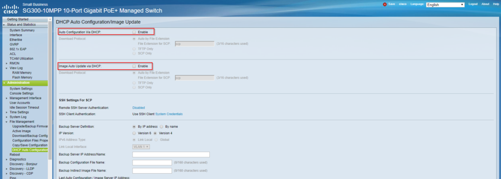
2147483592 2014-Aug-06 17:02:49 Warning %STP-W-PORTSTATUS: gi2: STP status Forwarding, aggregated (2)
2147483592 2014-Aug-06 17:02:49 Warning %STP-W-PORTSTATUS: gi2: STP status Forwarding, aggregated (2)
2147483593 2014-Aug-06 17:02:44 Informational %LINK-I-Up:  gi2, aggregated (2)
2147483594 2014-Aug-06 17:02:42 Warning %LINK-W-Down:  gi2, aggregated (2)
2147483595 2014-Aug-06 16:58:42 Informational %INIT-I-Startup: Cold Startup
2147483596 2014-Aug-06 16:58:40 Warning %STP-W-PORTSTATUS: gi2: STP status Forwarding
2147483597 2014-Aug-06 16:58:35 Informational %LINK-I-Up:  gi2
2147483598 2014-Aug-06 16:58:32 Warning %LINK-W-Down:  gi2
2147483599 2014-Aug-06 16:58:12 Warning %COPY-W-TRAP: The copy operation has failed, aggregated (1)
2147483600 2014-Aug-06 16:58:09 Alert %TFTP-A-TftpTxERROR: An error message was sent: 0 <Closed by application>, aggregated (1)
2147483601 2014-Aug-06 16:58:08 Informational %COPY-I-FILECPY: Files Copy - source URL tftp://192.168.39.49/boot\x64\wdsmgfw.efi destination URL flash://startup-config, aggregated (1)
Notice that the switch is trying to download a WDS boot file as the configuration file and probably encountered an error, then reboot itself. Did some research on the related configuration and found DHCP Auto Configuration/Image Update was ticked. Untick them and save configuration. Monitored for a couple of days, issue resolved.
Further optimization:
For whatever reason, this branch SMB switch should not be the root bridge, which should be the most reliable core switch, there are two ways to configure this:
Method 1: To ensure that a switch has the lowest bridge priority value, use the spanning-tree vlan vlan-id root primary command in global configuration mode. The priority for the switch is set to the predefined value of 24,576 or to the highest multiple of 4096 less than the lowest bridge priority detected on the network.
Method 2: Another method for configuring the bridge priority value is by using the spanning-tree vlan vlan-id priority value global configuration mode command. This command gives more granular control over the bridge priority value. The priority value is configured in increments of 4096 between 0 and 61,440. This command gives more granular control over the bridge priority value. The priority value is configured in increments of 4096 between 0 and 61,440.
https://www.cisco.com/assets/sol/sb/Switches_Emulators_v2_3_5_xx/help/250/index.html#page/tesla_250_olh/dhcp_auto_conf.html
http://www.ciscopress.com/articles/article.asp?p=2832407&seqNum=6