Configure Frame Relay
Step 1. Set the IP Address on the Interface
On a Cisco router, Frame Relay is most commonly supported on synchronous serial interfaces. Use the ip address command to set the IPv4 address of the interface.
Note: By default, Cisco IOS uses EUI-64 to automatically generate the IPv6 link-local address on an interface. Configuring static link-local addresses makes it easier to remember and identify the link-local addresses. IPv6 link-local addresses are used by IPv6 routing protocols for routing messages and next-hop addresses in the IPv6 routing table.
Step 2. Configure Encapsulation
The encapsulation frame-relay [cisco | ietf]
interface configuration command enables Frame Relay encapsulation and allows Frame Relay processing on the supported interface. There are two encapsulation options to choose from, cisco and ietf.
- The cisco encapsulation type is the default Frame Relay encapsulation enabled on supported interfaces. Use this option if connecting to another Cisco router. Many non-Cisco devices also support this encapsulation type. It uses a 4-byte header, with 2 bytes to identify the DLCI and 2 bytes to identify the packet type.
- The ietf encapsulation type complies with RFC 1490 and RFC 2427. Use this option if connecting to a non-Cisco router.
Step 3. Set the Bandwidth
Use the bandwidth command to set the bandwidth of the serial interface. Specify bandwidth in kb/s. This command notifies the routing protocol that bandwidth is statically configured on the link. The EIGRP and OSPF routing protocols use the bandwidth value to calculate and determine the metric of the link.
Step 4. Set the LMI Type (optional)
Manually setting the LMI type is optional, as Cisco routers autosense the LMI type by default. Recall that Cisco supports three LMI types: cisco, ANSI Annex D, and Q933-A Annex A. The default LMI type for Cisco routers is cisco.
The show interfaces serial command verifies the configuration, including the Layer 2 encapsulation of Frame Relay and the default LMI type of cisco. Notice that this command shows the IPv4 address, but does not include any of the IPv6 addresses.
Use the show ipv6 interface or the show ipv6 interface brief command to verify IPv6.
Note: The no encapsulation frame-relay command removes the Frame Relay encapsulation on the interface and returns the interface to the default HDLC encapsulation.
Configure Frame relay map
Dynamic mapping is performed by the Inverse ARP feature. Because Inverse ARP is enabled by default, no additional command is required to configure dynamic mapping on an interface.
Static mapping is manually configured on a router. Establishing static mapping depends on your network needs. To map between a next hop protocol address and a DLCI destination address, use the command:
frame-relay map protocol protocol-address dlci [broadcast]
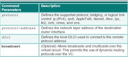
- The protocol -address is the other side address, the dlci is the one from local to the other router. For example.
 In the router R1, the command should be:
R1(config)# interface s0/0/1
R1(config-if)#bandwidth 64
R1(config-if)#ip address 10.1.1.1 255.255.255.0
R1(config-if)#ipv6 address 2001:DB8:CAFE:1::1/64
R1(config-if)#ipv6 address FE80::1 link-local
R1(config-if)#encapsulation frame-relay
R1(config-if)#frame-relay map ip 10.1.1.2 102 broadcast
R1(config-if)#frame-relay map ipv6 2001:DB8:CAFE:1::2 102
R1(config-if)#frame-relay map ipv6 FE80::2 102 broadcast
In the router R2, the command should be:
R2(config)# interface s0/0/1
R2(config-if)#bandwidth 64
R2(config-if)#ip address 10.1.1.2 255.255.255.0
R2(config-if)#ipv6 address 2001:DB8:CAFE:1::2/64
R2(config-if)#ipv6 address FE80::2 link-local
R2(config-if)#encapsulation frame-relay
R2(config-if)#frame-relay map ip 10.1.1.1 201 broadcast
R2(config-if)#frame-relay map ipv6 2001:DB8:CAFE:1::1 201
R2(config-if)#frame-relay map ipv6 FE80::1 201 broadcast
Frame Relay, ATM, and X.25 are non-broadcast multiaccess (NBMA) networks. NBMA networks do not support multicast or broadcast traffic, so a single packet cannot reach all destinations. This requires you to replicate the packets manually to all destinations. Using the broadcast keyword is a simplified way to forward routing updates.
Then specify the lmi type: R1(config-if)# frame-relay lmi-type ansi
Note: Some routing protocols may require additional configuration options. For example, RIP, EIGRP, and OSPF require additional configurations to be supported on NBMA networks.
Verify the Frame Relay
show frame-relay map
Configure subinterface
Most Frame Relay networks provide NBMA connectivity, using a hub-and-spoke topology, between remote sites. In an NBMA Frame Relay topology, when a single multipoint interface must be used to interconnect multiple sites, routing update reachability issues may result. With distance vector routing protocols, reachability issues may result from split horizon and multicast or broadcast replication. With link state routing protocols, issues with the DR/BDR election may result in reachability issues( Split Horizon stop some route from being advertised to other router).
Problem from Split Horizon
The split horizon rule is a loop prevention mechanism for distance vector routing protocols such as EIGRP and RIP. It is not applicable to link-state routing protocols. Split horizon rule reduces routing loops by preventing a routing update that is received on an interface from being forwarded out the same interface.
Note: Split horizon is not an issue if only one PVC (a single remote connection) is configured on a physical interface. This type of connection is point-to-point.
Problem1: routing update
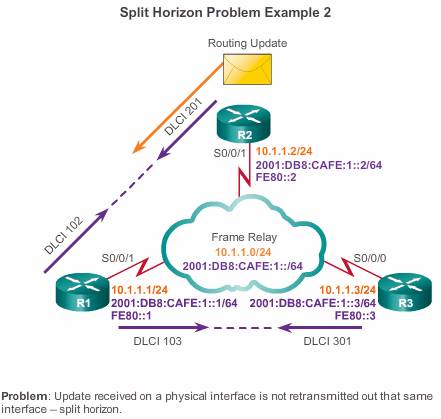 Figure above displays a similar example using the reference topology used throughout this chapter. R2, a spoke router, sends a routing update to R1, a hub router. R1 has multiple PVCs on a single physical interface. The split horizon rule prevents R1 from forwarding that routing update through the same physical interface to the other remote spoke router (R3).
Problem2:Multicast broadcast replication
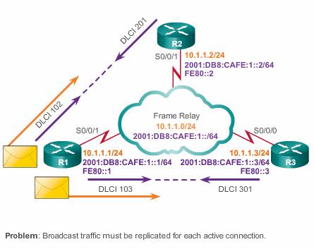 As shown in Figure above, due to split horizon, when a router supports multipoint connections over a single interface, the router must replicate broadcast or multicast packets. In the case of routing updates, the updates must be replicated and sent on each PVC to the remote routers. These replicated packets consume bandwidth and cause significant latency variations in user traffic. The amount of broadcast traffic and the number of VCs terminating at each router should be evaluated during the design phase of a Frame Relay network.
Problem: Neighbor Discovery: DR and BDR
Link-state routing protocols, such as OSPF, does not use the split horizon rule for loop prevention. However, reachability issues can arise with the DR/BDR. OSPF over NBMA networks works in non-broadcast network mode, by default, and neighbors are not automatically discovered. Neighbors can be statically configured. However, ensure that the hub router becomes a DR, as shown in Figure 4. Recall that a NBMA network behaves like Ethernet, and on Ethernet, a DR is needed to exchange routing information between all routers on a segment. Therefore, only the hub router can act as a DR, because it is the only router that has PVCs with all other routers.
Way to solve reach-ability issue
here are several ways to solve the routing reachability issue:
- Disable split horizon – One method for solving the reachability issues that are produced by split horizon may be to turn off split horizon. However, disabling split horizon increases the chances of routing loops in your network. Additionally, only IP allows the ability to disable split horizon; IPX and AppleTalk do not.
- Full meshed topology – Another method is to use a fully meshed topology; however, this topology increases costs.
- Subinterfaces (best way)– In a hub-and-spoke Frame Relay topology, the hub router can be configured with logically assigned interfaces called subinterfaces.
Subinterfaces
Using a subinterface configuration, each VC can be configured as a point-to-point connection. A partially meshed network can be divided into a number of smaller, fully meshed, point-to-point networks. Each point-to-point subnetwork can be assigned a unique network address. This allows each subinterface to act similarly to a leased line.
Frame Relay subinterfaces can be configured in either point-to-point or multipoint mode:
- Point-to-point– A single point-to-point subinterface establishes one PVC connection to another physical interface or subinterface on a remote router. In this case, each pair of the point-to-point routers is on its own subnet, and each point-to-point subinterface has a single DLCI. In a point-to-point environment, each subinterface is acting like a point-to-point interface. For each point-to-point VC, there is a separate subnet. Therefore, routing update traffic is not subject to the split horizon rule.
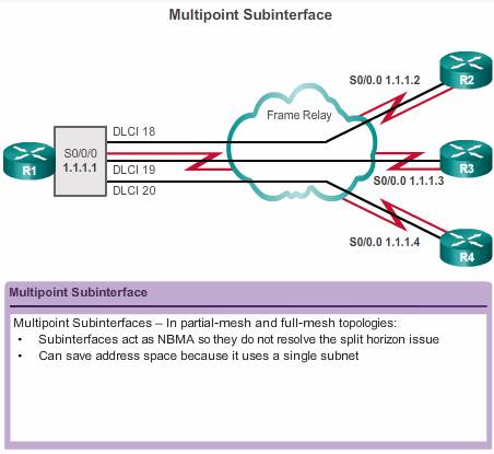
- Multipoint – A single multipoint subinterface establishes multiple PVC connections to multiple physical interfaces or subinterfaces on remote routers. All the participating interfaces are in the same subnet. The subinterface acts like an NBMA Frame Relay interface, so routing update traffic is subject to the split horizon rule. All multipoint VCs belong to the same subnet.
Configuring subinterfaces:
- The encapsulation frame-relay command is assigned to the physical interface.
- All other configuration items, such as the network layer address and DLCIs, are assigned to the subinterface.
The multipoint subinterface configurations can be used to conserve addresses. This can be especially helpful if Variable Length Subnet Masking (VLSM) is not being used. However, multipoint configurations may not work properly given the broadcast traffic and split horizon considerations. The point-to-point subinterface option was created to avoid these issues.
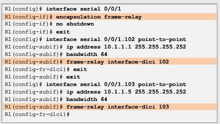
Configure point to point subinterface
To create a subinterface, in global configuration mode, use the interface serial command followed by the physical port number, a period (.), and the subinterface number.
R1(config)# interface serial 0/0/0.subinterface_number {multipoint|point-to-point}
Eg: R1(config-if)# interface serial 0/0/0.103 point-to-point
To make troubleshooting easier, use the DLCI as the sub-interface number. You must also specify whether the interface is point-to-multi point or point-to-point using either the multipoint or point-to-point keyword because there is no default.
If the subinterface is configured as point-to-point, the local DLCI for the subinterface must also be configured to distinguish it from the physical interface. The DLCI is also required for multipoint subinterfaces for which Inverse ARP is enabled for IPv4. It is not required for multipoint subinterfaces configured with static route maps.
The Frame Relay service provider assigns the DLCI numbers. These numbers range from 16 to 992, and usually have only local significance. The range varies depending on the LMI used.
The router(config-subinf)#frame-relay interface-dlci dlci_number command configures the local DLCI on the subinterface.
Note: Unfortunately, altering an existing Frame Relay subinterface configuration may fail to provide the expected result. In these situations, shut down the physical interface, make the appropriate changes to the subinterfaces and then re-enable the physical interface. If the corrected configuration produces unexpected results, then it may be necessary to save the configuration and reload the router.
To configure subinterfaces on a physical interface, the following steps are required:
Step 1. Remove any network layer address assigned to the physical interface. If the physical interface has an address, frames are not received by the local subinterfaces.
Step 2. Configure Frame Relay encapsulation on the physical interface using the encapsulation frame-relay command.
Step 3. For each of the defined PVCs, create a logical subinterface. Specify the port number, followed by a period (.) and the subinterface number. To make troubleshooting easier(not mandatory), it is suggested that the subinterface number matches the DLCI number.
Step 4. Configure an IP address for the interface and set the bandwidth.
Step 5. Configure the local DLCI on the subinterface using the frame-relay interface-dlci command. Recall that the Frame Relay service provider assigns the DLCI numbers