Configuring a Cisco Router as a Frame Relay Switch
Cisco routers can be configured as dedicated Frame Relay switches that act as DCE devices. On a Cisco router configured as a Frame Relay switch, frames from a Frame Relay PVC arriving on an incoming interface are switched to a Frame Relay PVC on outgoing interface. During this process, the incoming DLCI in the arriving frames is replaced by an outgoing DLCI. Frame Relay switching is performed completely in Layer 2, and the Frame Relay switch pays no attention to Layer 3 information contained within the frames. The paths taken by the switched frames are completely based on the Frame Relay route table constructed.
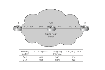
We use a simple example depicted bellow:
Frame Relay Switching Using a Cisco Router
The simple Frame Relay network in Figure 4-4 shows a Cisco router configured as a Frame Relay switch with two serial interfaces set up as DCE interfaces. The Cisco router behaving as a Frame Relay switch switches Frame Relay frames received from interface serial4/3 on DLCI 403 to interface serial4/1 on the outgoing DLCI to 304. Example 4-25 shows the sample configurations for the router configured as a Frame Relay switch.
Example 4-25 Configurations for Frame Relay Switch
SW#show running-config
Building configuration...
<output omitted>
!
hostname SW
!
<output omitted>
!
frame-relay switching
!
interface Serial4/1
 no ip address
 encapsulation frame-relay
 clockrate 64000
 frame-relay intf-type dce
 frame-relay route 304 interface Serial4/3 403
!
interface Serial4/3
 no ip address
 encapsulation frame-relay
 clockrate 64000
 frame-relay intf-type dce
 frame-relay route 403 interface Serial4/1 304
To configure a Cisco router as a Frame Relay switch, follow the configuration steps listed below:
| Step 1 | Enable Frame Relay switching on the router using the command frame-relay switching in the global configuration mode. |
| Step 2 | Go to the interface configuration mode of the Frame Relay interface where you want to configure Frame Relay switching. Configure the interface as a DCE interface with the frame-relay intf-type dce interface configuration command. |
| Step 3 | Configure the Frame Relay switching on the interface using the frame-relay route command, specifying the incoming DLCI, the outgoing interface, and the outgoing DLCI. Note that Frame Relay switching can be configured only on physical interfaces. |
| Step 4 | The clockrate command is required on the serial interface of the Frame Relay switch (attached with the DCE end of the serial cable). It provides clocking signals to the connected Frame Relay routers, which are set up as DTE devices. |
The frame-relay route interface configuration command is used to route an incoming DLCI to an outgoing interface and corresponding outgoing DLCI.
To verify the contents of the Frame Relay route table, the show frame-relay route privileged EXEC mode command is used. Example 4-26 shows the contents of the table displayed by the show frame-relay route command.
Example 4-26 Contents of show frame-relay route Command
SW#show frame-relay route
Input Intf   Input Dlci   Output Intf   Output Dlci  Status
Serial4/1    304       Serial4/3    403      active
Serial4/3    403       Serial4/1    304      active
SW#
NOTE
Take note that the frame-relay route command must be configured in pairs on both the incoming interface and outgoing interface for the Frame Relay route to become active.
