If a router or router interface (that serves as a default gateway) fails, the hosts configured with that default gateway are isolated from outside networks.In practice, it is common for a multilayer switch to act as the default gateway for each VLAN in a switched network.
This discussion focuses on the functionality of routing, regardless of the physical device used.
End devices are typically configured with a single IP address for a default gateway. This address does not change when the network topology changes.
Router Redundancy
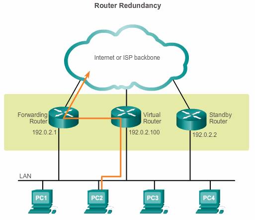
To implement this type of router redundancy, multiple routers are configured to work together to present the illusion of a single router to the hosts on the LAN, as shown in the figure. By sharing an IP address and a MAC address, two or more routers can act as a single virtual router.
The IP address of the virtual router is configured as the default gateway for the workstations on a specific IP segment.
Virtual router: a set of routers working together to present the illusion of a single router to the hosts on a LAN segment.
Forwarding router: a device that is part of a virtual router group assigned to the role of default gateway.
Standby router: a device that is part of a virtual router group assigned the role of alternate default gateway.
Virtual MAC address: the layer 2 address returned by ARP for an FHRP gateway.
There are two version of HSRP.
+ With HSRP version 1, the virtual router’s MAC address is 0000.0c07.ACxx , in which xx is the HSRP group.
+ With HSRP version 2, the virtual MAC address if 0000.0C9F.Fxxx, in which xxx is the HSRP group.
Note: Another case is HSRP for IPv6, in which the MAC address range from 0005.73A0.0000 through 0005.73A0.0FFF.
How it works
Normal working:
1. When frames are sent from host devices to the default gateway, the hosts use ARP to resolve the MAC address that is associated with the IP address of the default gateway. The ARP resolution returns the MAC address of the virtual router, which is the Active Virtual Gateway (AVG).
2. Frames that are sent to the MAC address of the virtual router can then be physically processed by the currently active router within the virtual router group. A protocol is used to identify two or more routers as the devices that are responsible for processing frames that are sent to the MAC or IP address of a single virtual router.
3. Host devices send traffic to the address of the virtual router. The physical router that forwards this traffic is transparent to the host devices.
These are the steps that take place when the active router fails:

1. The standby router stops seeing Hello messages from the forwarding router.
2. The standby router assumes the role of the forwarding router.
3. Because the new forwarding router assumes both the IP and MAC addresses of the virtual router, the host devices see no disruption in service.
Redundancy protocols
A redundancy protocol provides the mechanism for determining which router should take the active role in forwarding traffic. It also determines when the forwarding role must be taken over by a standby router. The transition from one forwarding router to another is transparent to the end devices.
The ability of a network to dynamically recover from the failure of a device acting as a default gateway is known as first-hop redundancy.
- Hot standby Router Protocol (HSRP) : Cisco-proprietary FHRP. HSRP is used in a group of routers for selecting an active device and a standby device. In a group of device interfaces, the active device is the device that is used for routing packets; the standby device is the device that takes over when the active device fails, or when pre-set conditions are met.An HSRP active router has the following characteristics:
- Responds to default gateway’s ARP requests with the virtual router’s MAC.
- Assumes active forwarding of packets for the virtual router.
- Sends Hello messages (every 3 second, dead timer is 10 seconds).
- Knows the virtual router IP address.
An HSRP standby router has the following characteristics:
- Listens for periodic Hello messages.
- Assumes active forwarding of packets if it does not hear from the active router.
Verify:
show standby- + HSRP is Cisco proprietary which allows several routers or multilayer switches to appear as a single gateway IP address.
+ HSRP has 5 states: Initial, listen, speak, standby and active.
+ HSRP allows multiple routers to share a virtual IP and MAC address so that the end-user hosts do not realize when a failure occurs.
+ The active (or Master) router uses the virtual IP and MAC addresses.
+ Standby routers listen for Hellos from the Active router. A hello packet is sent every 3 seconds by default. The hold time (dead interval) is 10 seconds.
+ Virtual MAC of 0000.0C07.ACxx , where xx is the hexadecimal number of HSRP group.
+ The group numbers of HSRP version 1 range from 0 to 255. HSRP does support group number of 0 (we do check it and in fact, it is the default group number if you don’t enter group number in the configuration) so HSRP version 1 supports up to 256 group numbers. HSRP version 2 supports 4096 group numbers.
- HSRP for IPv6 – Cisco-proprietary FHRP providing the same functionality of HSRP, but in an IPv6 environment.
Periodic router advertisements (RAs) are sent for the HSRP virtual IPv6 link-local address when the HSRP group is active. When the group becomes inactive these RAs stop after a final RA is sent. - Virtual Router Redundancy Protocol version 2 (VRRPv2) – A non-proprietary election protocol that dynamically assigns responsibility for one or more virtual routers to the VRRP routers on an IPv4 LAN. This allows several routers on a multiaccess link to use the same virtual IPv4 address. A VRRP router is configured to run the VRRP protocol in conjunction with one or more other routers attached to a LAN. In a VRRP configuration, one router is elected as the virtual router master, with the other routers acting as backups, in case the virtual router master fails.
- VRRPv3 – Provides the capability to support IPv4 and IPv6 addresses. VRRPv3 works in multi-vendor environments and is more scalable than VRRPv2.
GLBP
Gateway Load Balancing Protocol (GLBP) – Cisco-proprietary FHRP that protects data traffic from a failed router or circuit, like HSRP and VRRP, while also allowing load balancing (also called load sharing) between a group of redundant routers.
In HSRP and VRRP, only the active router in HSRP and VRRP groups forwards traffic for the virtual MAC address. Resources that are associated with the standby router are not fully utilized. You can accomplish some load balancing with these protocols by creating multiple groups and assigning multiple default gateways, but this configuration creates an administrative burden.
With GLBP, you can fully utilize resources without the administrative burden of configuring multiple groups and managing multiple default gateway configurations.
When the routers are configured to a GLBP group, they first elect one gateway to be the Active Virtual Gateway (AVG) for that group. The election is based on the priority of each gateway (highest priority wins). If all of them have the same priority then the gateway with the highest real IP address becomes the AVG. The AVG, in turn, assigns a virtual MAC address to each member of the GLBP group. Each gateway which is assigned a virtual MAC address is called Active Virtual Forwarder (AVF). A GLBP group only has a maximum of four AVFs. If there are more than 4 gateways in a GLBP group then the rest will become Standby Virtual Forwarder (SVF) which will take the place of a AVF in case of failure.
The virtual MAC address in GLBP is 0007.b400.xxyy where xx is the GLBP group number and yy is the different number of each gateway (01, 02, 03…).
|
Note:
|
GLBP has the following characteristics:
- Allows full use of resources on all devices without the administrative burden of creating multiple groups.
- Provides a single virtual IP address and multiple virtual MAC addresses.
- Routes traffic to single gateway distributed across routers.
- Provides automatic rerouting in the event of any failure.
Use the show glbp command to verify the GLBP status.
- GLBP for IPv6 – Cisco-proprietary FHRP providing the same functionality of GLBP, but in an IPv6 environment.
- ICMP Router Discovery Protocol (IRDP) – Specified in RFC 1256, is a legacy FHRP solution. IRDP allows IPv4 hosts to locate routers that provide IPv4 connectivity to other (nonlocal) IP networks.
For more, check here: http://www.9tut.com/gateway-load-balancing-protocol-glbp-tutorial
Configuration
HSRP (more)
Priority value: highest priority to immediately become the active router. Priority is determined first by the configured priority value, and then by the IP address.
eg. For router 2, HSRP group 10, priority 110, IP address 172.16.10.3, virtual IP address 172.16.10.1
R2(config)# interface g0/1
R2(config-if)#ip address 172.16.10.3 255.255.255.0 //real IP
R2(config-if)#no shutdown
R2(config-if)#standby 10 ip 172.16.10.1 //group number and virtual IP
R2(config-if)#standby 10 priority 110 //priority value
R2(config-if)#end
For router 1, HSRP group 10, priority 150, IP address 172.16.10.3, virtual IP address 172.16.10.1
R1(config)# interface g0/1
R1(config-if)#ip address 172.16.10.2 255.255.255.0 //real IP
R1(config-if)#no shutdown
R1(config-if)#standby 10 ip 172.16.10.1 //group number and virtual IP
R1(config-if)#standby 10 priority 150 //priority value
R1(config-if)#end
R1#show standby brief
P indicates configured to preempt
Interface Grp Pri p state Active Standby Virtual IP
Gi0/1 10 150 Active local 172.16.10.3 172.16.10.1
R1#show run int g10/1
…….
ip address 172.16.10.2 255.255.255.0
standby 10 ip 172.16.10.1
standby 10 priority 150
…….
GLBP
We use the example above to configure First Hop Redundancy using GLBP, Router 1 priority value 150, virtual IP 172.16.10.1 , IP address 172.16.10.2 255.255.255.0
R1(config)# interface g0/1
R1(config-if)#no standby 10
R2(config)#interface g0/1
R2(config-if)#no standby 10
Now, you should configure the a host PC with default gateway of 172.16.10.1
R1(config-if)#glbp 10 ip 172.16.10.1 //group number and virtual IP
R1(config-if)#glbp 10 preempt //To configure the gateway to take over as active virtual gateway (AVG) for a Gateway Load Balancing Protocol (GLBP) group if it has higher priority than the current AVG
R1(config-if)#glbp 10 priority 150 //priority value
R1(config-if)#glbp 10 load-balancing round-robin
R1(config-if)#end
R1# show glbp brief
Or R1# show glbp
configure GLBP on R2
R2(config)#interface g0/1
R2(config-if)#glbp 10 ip 172.16.0.1 //group number and virtual IP, note that it is same as the one in R1
R2(config-if)#glbp 10 load-balancing round-robin
By now, you should configure host PC with default-gateway of 172.16.0.1, which is the virtual interface.