A network running CST (common spanning tree) has these characteristics:
- No load sharing is possible. One uplink must block for all VLANs.
- The CPU is spared. Only one instance of spanning tree must be computed.
PVST+( IEEE 802.1D)
Characteristics of PVST:
- It is possible for one trunk port on a switch to be blocking for a VLAN while not blocking for other VLANs.
- PVST+ can be used to implement Layer 2 load balancing.
- Drawbacks: Because each VLAN runs a separate instance of STP, the switches in a PVST+ environment require greater CPU process and BPDU bandwidth consumption than a traditional CST implementation of STP. This would only be problematic if a large number of VLANs are configured.
PVST+ Operation
For each VLAN in a switched network, PVST+ performs four steps to provide a loop-free logical network topology:
1. Elects one root bridge – Only one switch can act as the root bridge (for a given VLAN). The root bridge is the switch with the lowest bridge ID. On the root bridge, all ports are designated ports (in particular, no root ports).
2. Selects the root port on each non-root bridge – STP establishes one root port on each non-root bridge. The root port is the lowest-cost path from the non-root bridge to the root bridge, indicating the direction of the best path to the root bridge. Root ports are normally in the forwarding state.
3. Selects the designated port on each segment – On each link, STP establishes one designated port. The designated port is selected on the switch that has the lowest-cost path to the root bridge. Designated ports are normally in the forwarding state, forwarding traffic for the segment.
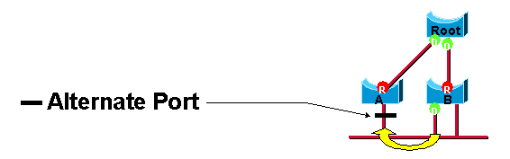
4. The remaining ports in the switched network are alternate ports – Alternate ports normally remain in the blocking state, to logically break the loop topology. When a port is in the blocking state, it does not forward traffic, but can still process received BPDU messages.
RSTP (IEEE 802.1w)
RSTP supports a new port type: alternate port( backup port) in discarding state. Notice that there are no blocking ports. RSTP does not have a blocking port state.
RSTP defines port states as discarding, learning, or forwarding.
Alternate port: Similar to the blocking ports in STP.
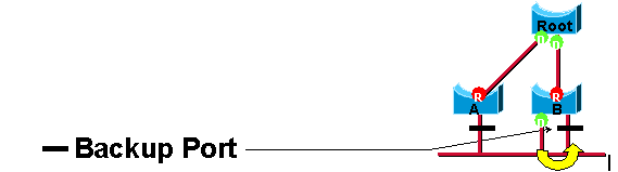
Backup port:
Port in the same collision domain, how to determine backup port?
To choose the designated port, the decision process involves the following parameters inside the BPDU:
* Lowest path cost to the Root
* Lowest Sender Bridge ID (BID)
* Lowest Port ID
So on Switch B if the left port is F0/1 , the right side port is F0/3, the F0/1 will be the designated port and F0/2 will be the backup port.
Characteristics:
RSTP can achieve much faster convergence in a properly configured network, sometimes in as little as a few hundred milliseconds. RSTP redefines the type of ports and their state. If a port is configured to be an alternate port or a backup port, it can immediately change to forwarding state without waiting for the network to converge.
characteristics:
- RSTP is the preferred protocol for preventing Layer 2 loops in a switched network environment. Many of the differences were established by Cisco-proprietary enhancements to the original 802.1D. These enhancements, such as BPDUs carrying and sending information about port roles only to neighboring switches, require no additional configuration and generally perform better than the earlier Cisco-proprietary versions. They are now transparent and integrated in the protocol’s operation.
- Cisco-proprietary enhancements to the original 802.1D, such as UplinkFast and BackboneFast, are not compatible with RSTP.
- RSTP (802.1w) supersedes the original 802.1D while retaining backward compatibility. Much of the original 802.1D terminology remains and most parameters are unchanged. In addition, 802.1w is capable of reverting back to legacy 802.1D to interoperate with legacy switches on a per-port basis. For example, the RSTP spanning tree algorithm elects a root bridge in exactly the same way as the original 802.1D.
- RSTP keeps the same BPDU format as the original IEEE 802.1D, except that the version field is set to 2 to indicate RSTP, and the flags field uses all 8 bits.
- RSTP is able to actively confirm that a port can safely transition to the forwarding state without having to rely on any timer configuration.
Fast RSTP+ DPDU
A switch running RSTP can communicate directly with a switch running the original 802.1D STP. RSTP sends BPDUs and populates the flag byte in a slightly different manner than in the original 802.1D:
- Protocol information can be immediately aged on a port if Hello packets are not received for three consecutive Hello times, six seconds by default, or if the max age timer expires.
- Because BPDUs are used as a keepalive mechanism, three consecutively missed BPDUs indicate lost connectivity between a bridge and its neighboring root or designated bridge. The fast aging of the information allows failures to be detected quickly.

- Bits 0 and 7 are used for topology change and acknowledgment as they are in the original 802.1D.
- Bits 1 and 6 are used for the Proposal Agreement process (used for rapid convergence).
- Bits from 2 to 5 encode the role and state of the port.
- Bits 4 and 5 are used to encode the port role using a 2-bit code.
Edge port
An RSTP edge port is a switch port that is never intended to be connected to another switch device.It should be connected to a end station.
- Will never have a switch connected to it
- Immediately transitions to forwarding
- Functions similarly to a port configured with Cisco PortFast
- On a Cisco switch configured using the
spanning-tree portfastcommand
Configuring an edge port to be attached to another switch is not recommended. This can have negative implications for RSTP because a temporary loop may result, possibly delaying the convergence of RSTP.
Cisco PortFast technology is useful for DHCP.
Without PortFast, a PC can send a DHCP request before the port is in forwarding state, denying the host from getting a usable IP address and other information. Because PortFast immediately changes the state to forwarding, the PC always gets a usable IP address.
Link types
Depending on what is attached to each port, two different link types can be identified:
- Point-to-Point – A port operating in full-duplex mode typically connects a switch to a switch and is a candidate for rapid transition to forwarding state.
- Shared – A port operating in half-duplex mode connects a switch to a hub that attaches multiple devices.
The link type can determine whether the port can immediately transition to forwarding state, assuming certain conditions are met. These conditions are different for edge ports and non-edge ports. Non-edge ports are categorized into two link types, point-to-point and shared. The link type is automatically determined, but can be overridden with an explicit port configuration using the
spanning-tree link-type parameter command.
Characteristics of port roles with regard to link types include the following:
- Root ports do not use the link-type parameter. Root ports are able to make a rapid transition to the forwarding state as soon as the port is in sync.
- Alternate and backup ports do not use the link-type parameter in most cases.
- Designated ports make the most use of the link-type parameter. Rapid transition to the forwarding state for the designated port occurs only if the link-type parameter is set to point-to-point.
PVST+ configuration

1. Configure Root bridge
To ensure that the switch has the lowest bridge priority value, use the
S1(config)# spanning-tree vlan vlan-id root primary
OR
S1(config)# spanning-tree vlan vlan-id priority value
command in global configuration mode. The priority for the switch is set to the predefined value of 24,576 or to the highest multiple of 4,096, less than the lowest bridge priority detected on the network.
If an alternate root bridge is desired, use the
S1(config)#spanning-tree vlan vlan-id root secondary
2 . PortFast and BPDU guard
To configure PortFast on a switch port:
S1(conf-if)# spanning-tree portfast
Enables PortFast on all non-trunking interfaces:
S1(config)# spanning-tree portfast default
BPDU guard.
When it is enabled, BPDU guard puts the port in an error-disabled state on receipt of a BPDU. This will effectively shut down the port. The BPDU guard feature provides a secure response to invalid configurations because you must manually put the interface back into service.
S1(conf-if)# spanning-tree bpduguard enable
Enables BPDU guard on all PortFast-enabled ports:
S1(config)# spanning-tree portfast bpduguard default
Rapid PVST+
S1(config)# Spanning-tree mode rapid-pvst
S1(config)# interface f0/1
S1(config-if)#spanning-tree link-type point-to-point
S1(config-if)#end
S1#clear spanning-tree detected-protocols //clean all detected STP
Analyze STP
To analyze the STP topology, follow these steps:
Step 1. Discover the Layer 2 topology. Use network documentation if it exists or use the show cdp neighbors command to discover the Layer 2 topology.
Step 2. After discovering the Layer 2 topology, use STP knowledge to determine the expected Layer 2 path. It is necessary to know which switch is the root bridge.
Step 3. Use the show spanning-tree vlan command to determine which switch is the root bridge.
Step 4. Use the show spanning-tree vlan command on all switches to find out which ports are in blocking or forwarding state and confirm your expected Layer 2 path.
A big part of troubleshooting consists of comparing the actual state of the network against the expected state of the network and spotting the differences to gather clues about the troubleshooting problem.
Two types of failure.
- The first is similar to the OSPF problem; STP might erroneously block ports that should have gone into the forwarding state. Connectivity might be lost for traffic that would normally pass through this switch, but the rest of the network remains unaffected.
- The second type of failure is much more disruptive. It happens when STP erroneously moves one or more ports into the forwarding state.