Hello/hold timers
Cisco IOS does not prevent you from making the unfortunate configuration choice of setting the Hold Timer to a value smaller than the Hello interval. In such a case, the neighborship repeatedly fails and recovers, flapping routes in and out of the routing table.
To verify the timers, use command:
show ip eigrp interfaces detail type number
eg. show ip eigrp interfaces detail fa0/1
Control neighborships with static configuration
Although seldom used, static configuration can reduce the overhead associated with EIGRP multicast message.
Frame relay might benefit from it because to support multicasts and broadcasts over Frame Relay, a router must replicate a frame and send a copy over PVC associated with the interface or subinterface.
For example, if a multipoint subinterface has ten PVCs associated with it, but only two of the remote routers used EIGRP, without static nieghbors, all ten routers would be sent a copy of the EIGRP multicast HELLO packets.
Configure static EIGRP neighbors
To define a neighbor, both routers must configure the neighbor ip-address outgoing_interface EIGRP router subcommand.
- ip-address is the interface IP address of the neighboring router.
- EIGRP configuration still needs a network command that matches the interface referenced by the neighbor command
Note that the show ip eigrp neighbors command doesn’t identify a neighbor as static, but the show ip eigrp neighbors detail command does.
Because of the EIGRP neighbor command, if at least one EIGRP static neighbor is defined on an interface, no dynamic neighbors can be either discovered or continue to work if already discovered, which means the static one take precedence.
eg. the router has been configured as following
Router# show ip eigrp neighbors detail

EIGRP-IPv4 VR(foo) Address-Family Neighbors for AS(1)
H   Address                 Interface       Hold Uptime   SRTT   RTO  Q  Seq
                                            (sec)         (ms)       Cnt Num
1   192.168.10.2                 Gi2/0             11 00:00:21 1600  5000  0  4
0   192.168.10.1                 Gi2/0             12 00:00:21 1600  5000  0  3
192.168.10.2 is the R2 interface IP address, 192.168.10.1 is the R1 interface IP address.
If you add a command neighbor 192.168.10.4 G2/0 , Router will lose its current neighborships with R1 and R2.
Configuration settings that could prevent neighbor relationships
Neighbor requirements for EIGRP and OSPF
| Requirement | EIGRP | OSPF |
| The routers must be able to send/receive IP packets to one another | Yes | Yes |
| Interface’s primary IP addresses must be in the same subnet | Yes | Yes |
| Must not be passive | Yes | Yes |
| Must use the same ASN(EIGRP) or Process-ID (OSPF) in the router configuration command | Yes | No |
| Hello interval/timer, hold(EIGRP) or Dead (OSPF) timer | No | Yes |
| Must pass neighbor authentication( if requred) | Yes | Yes |
| Same area | N/A | Yes |
| IP MTU must match | No | Yes |
| K-value must match | Yes | N/A |
| Router ID must be unique | No1 | Yes |
1 DUplicate EIGRP RIDs don’t prevent routers from becoming neighbors, but it can cause problems when adding external EIGRP routes to the IP routing table.
Configure EIGRP Metric components
EIGRP uses this formula to calculate the Metric:
- The unit for the leastbandwidth is kbps,
- The unit for delay is “tens of microseconds”,0.1 mSec.
You can use the output of the show interfaces command, find the DLY xxx usec, take that xxx number and divide by 10.
+ usec/µsec is microsecond, 1/1000th of a milisecond, or 1000 nanoseconds.
We can use five weighting constants, called K-values, which are represented in the metric calculation formula as constants K1, K2, K3, K4, and K5.
The complete composite Formula:
- The unit for the leastbandwidth is kbps,
- The unit for delay is “tens of microseconds”,0.1 mSec.
Neighborship over WANs
Neighborship on Frame Relay
Neighborship can only form when a PVC exists between the two routers.
Neighborship on MPLS VPN
The Service provider cloud ( Privider Edge routers) are layer 3 aware, which means that the customer edge (CE) routers form an EIGRP neighborship with the PE routers on the other end of their local access link. The PE routers exchange their routes, typically using Multiprotocol BGP (MP-BGP).
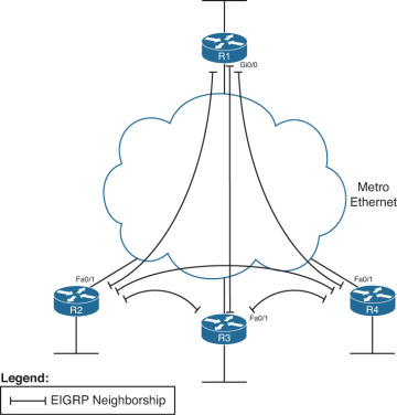
Neighborship on Metro Ethernet (MetroE)
The Metro Ethernet is a Layer 2 service, needs other technologies such as Virtual Private Wire Service(VPWS) and Virtual Private LAN service (VPLS)
The VPWS focuses on point to point protocols, whereas VPLS supports multipoint, approximating the concept of the entire WAN service acting like one large Ethernet Switch.
Because it’s a layer 2 service, it does not have layer 3 awareness, customer premises equipment see the MetroE service as a VLAN. As a result all the routers connected to the MetroE can become EIGRP neighbors.
EIGRP topology table
Each EIGRP router add topology data for some prefixes so that it can then advertise these routes to its EIGRP neighbors. A router’s EIGRP process adds subnets to its local topology table, without learning the topology data from an EIGRP neighbor, from thress sources:
- The network command.
- The neighbor command.
- Learned by redistribution of routes into EIGRP.
Eventually, all routers in the EIGRP domain learn about all prefixes unless some other feature that can alter the flow of topology information: route summarization or route filtering.
Content of EIGRP update message
Five basic protocol messages : hello, update, query, reply, ACK
Topology data exchange process:
- Update: contains the topology information, which includes
- prefix,
- prefix length,
- metric components ( bandwidth, delay, reliability, and load),
- nonmetric items( MTU and hop count)
- ACK: receipt of the update packet.
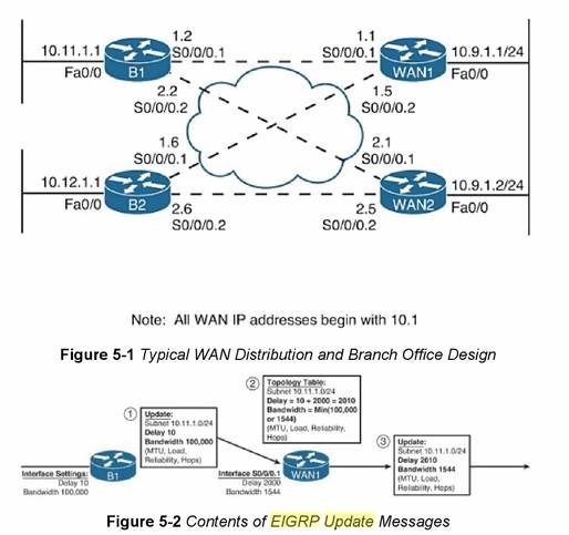
Step 1, B1 advertises the prefix (10.11.1.0/24) using an EIGRP update message. The message includes the four metric components, plus MTU and hop count.
Step2, WAN1 receives the update message and adds the topology information for 10.11.1.0/24 to its own EIGRP topology table, with these changes:
- WAN1 considers the interface on which it received the update(s0/0/0.1) to be the outgoing interface of a potential route to reach 10.11.1.0/24
- WAN1 adds the delay of s0/0/0.1 (2000 tens-of-microseconds) to the delay listed in the update message.
- WAN1 compares the bandwidth of S0/0/0.1 (1544 kbps per second) to the bandwidth listed in the update message(100,000kbps) and chooses the lower value(1544) as the bandwidth for this route.
- WAN1 also update load(highest value), reliability (lowest value), and MTU ( lowest value) based on comparisons, and add 1 to the hop count.
Step3, WAN1 then sends an update to its neighbors, with the metric components listed in their own topology table.
The EIGRP update process
- When a neighbor first comes up, the routers exchange full updates.
- If no changes occur in the network, no reflooding of topology data.
- If something changes the routers send partial updates about only the prefixes whoes status or metric components have changed.
- If neighbor fail and then recover, full update occur.
- EIGRP uses split horizon rules on most interfaces by default, which impacts exactly which topology data EIGRP sends during both full and partial updates.
EIGRP uses reliable transport protocol (RTP) to send the EIGRP updates and confirm their receipt. RTP set timers so that the sender of an update waits a reasonable time, but not too long, before deciding whether all neighbors received the update or whether one or more neighbors did not reply with an ACK.
WAN issue for EIGRP message change
Frame-relay neighborship: split-horizon can prevent the routers of forming neighbor.
Solution:
- Point-to-point subinterface.
- full-mesh PVCs
- disable split-horizon:
- RIP:
no ip split-horizon - EIGRP:
no ip split-horizon eigrp asn
- RIP:
EIGRP WAN bandwidth control
Mainly for Frame-relay, when hundreds or even thousands of PVCs configured on an interface, the frame-relay access link may over load the link.
To adjust the bandwidth of interface/subinterface:
bandwidth speed_inkbps
The command define the maximum weight of EIGRP message traffic in the interface bandwidth:
r1(config-if)# ip bandwidth-percent eigrp asn percent interface
a few caveats to keep in mind when trying to limit the bandwidth consumed by EIGRP:
■ The IOS default for bandwidth serial interfaces and subinterfaces is 1544 (Kbps).
■ EIGRP limits the consumed bandwidth based on the percentage of interface/subinterface bandwidth.
■ This feature keys on the bandwidth of the interface or subinterface through which the neighbor is reachable, so don’t set only the physical interface bandwidth and forget the subinterfaces.
■ Recommendation: Set the bandwidth of point-to-point links to the speed of the Committed Information Rate (CIR) of the single PVC on the subinterface.
■ General recommendation: Set the bandwidth of multipoint subinterfaces to around the total CIR for all VCs assigned to the subinterface.
■ Note that for multipoint subinterfaces, IOS WAN bandwidth control first divides the subinterface bandwidth by the number of configured PVCs and then determines the EIGRP percentage based on that number.
Metric Tuning
Refer to the formula, we can change the metrics in following ways:
- Interface bandwidth
- Interface delay
- Configure K values
- add to the calucated metric using offset lists.
In practice, the most reasonable and commonly used methods are to set the delay and bandwidth.
Between these two, setting delay value is a better choice. Because IOS uses the bandwidth setting for other reasons:
- Calculating interface utilization
- For QoS parameters
- For SNMP statistics reporting
- Impact the choice of best route.
| Interface type | Bandwidth (Kbps) | Delay ( Microseconds) |
| Serial | 1544 | 20,000 |
| GigE | 1,000,000 | 10 |
| FastE | 100,000 | 100 |
| Ethernet | 10,000 | 1000 |
Offset Lists
It will allow you to calculate integer metric for a given prefix. An Offset List can perform the following functions:
■ Match prefixes/prefix lengths using an IP ACL, so that the offset is applied only to routes matched by the ACL with a permit clause
■ Match the direction of the Update message, either sent (out) or received (in)
■ Match int interface on which the Update is sent or received
■ Set the integer metric added to the calculation for both the FD and RD calculations for the route
offset-list {access-list-number | access-list-name} {in | out} offset [interface-type interface-number]
Eg. let’s use this figure again:
If we add the offset lists:
WAN1(config)# access-list 11 permit 10.11.1.0
WAN1(config)# router eigrp 1
WAN1(config-router)# offset-list 11 in 3 Serial0/0/0.1
The offset we set here is 3.
Now the RD will become 28163, and the FD will become 2,172,419, we can get this by the command : show ip eigrp topo 10.11.1.0/24
……
10.1.1.2 (Serial0/0/0.1), from 10.1.1.2, Send flag is 0x0
Composite metric is (2172419/28163), Route is Internal
…………