Review on OSPF configuration
http://frankfu.click/networking/networking-fundamental/single-area-ospf/
http://frankfu.click/networking/cisco/multi-area-ospf-summary-address-vs-area-range/
Neighbors and adjacencies on LANs
Requirements for neighbor forming:
- OSPF has been enabled on the interface. Either through the network router subcommand or the ip ospf area interface subcommand.
- The interface has not been made passive by the passive-interface router.
If both requirements are met, OSPF sends Hellos to the 224.0.0.5 multicast address. In the Hello packet, OSPF RID of sending router, OSPF area.
Another command that impacts the neighbors is :
R1(config-if)# ip ospf process-id area area-id
neighborship requirement for OSPF and EIGRP : http://frankfu.click/networking/cisco/ccnp/eigrp-ccnp/
Router ID:
All router RID should be unique. An OSPF RID mismatch can cause unpredictable results, because OSPF reouters base their view of the topology on the topology database, and the database identifies routers based on their RIDs.
The routers with duplicate RIDs do not form neighborship with each other.
MTU:
MTU tells the IOS the largest IP packet that can be forwarded out an interface. This setting protects the packet from being discarded on data links whose Layer 2 features will not pass a frame over a certain size.
When a router needs to forward a packet larger than the outgoing interface’s MTU, the router either fragments the packet or discards it. If the IP header’s Do not Fragment (DF) bit is set, the router discards the packet. If the DF bit is not set, the router can perform Layer 3 fragmentation on the packet, creating two or more IP packets with mostly identical IP headers, spreading the data that follows the original IP packet header out among the fragments.
The MTU used by all devices attached to the same data link ought to be the same value. However, routers have no dynamic mechanism to prevent the misconfiguration of MTU on neighboring routers.
When an MTU mismatch occurs between two OSPF neighbors, one router will attempt to become neighbors with other router whose MTU differs. The other router will be listed in the list of neighbors. However, the two routers will not exchange topology information, and the two routers will not calculate routers that use this neighbor as a next-hop router.
Note, mismatched MTU does not prevent routers from becoming neighbors, but it does prevent them from exchanging topology data.
The state will moves from INIT(initializing) to EXSTART( starting database exchange) then DOWN, never forms FULL state.
To set the MTU value:
R1(config-if)# ip mtu value
OSPF neighbors and adjacencies on WANs
Besides the requirement for LANs, the operation of OSPF on WAN links needs some additional thought.
- Will the routers discover each other using multicast OSPF Hello messages, or do the neighbors require predefinition?
- Will the routers try to elect a DR, and if so, which router should be the DR?
- With which other routers should each router become an OSPF neighbor?
The first two questions depend on the setting of the OSPF network type, the third question depends on the WAN service.
Network Type:
| Interface Type | Uses DR/BDR ? | Default Hello interval | Dynamic Discovery of Neighbors? | More than two routers allowed in the subnet? |
| Broadcast | Y | 10 | Y | Y |
| Point-to-point | N | 10 | Y | N |
| Loopback | N | – | – | N |
| Nonbroadcast (NBMA) | Y | 30 | N | Y |
| Point-to-multipoint | N | 30 | Y | Y |
| Point-to-multipoint Nonbroadcast | N | 30 | N | Y |
You can set the network type in interface subconfiguration mode:
R1(config-if)# Ip ospf network { non-broadcast | broadcast | point-to-point | point-to-multipoint }
To verify the network type by command: show ip ospf interface.
on MPLS VPN
The customer routers connect to the service, often with serial links but at other times with Frame Relay PVCs or with Ethernet.
The Provider edge (PE) routers are Layer 3 aware.
Layer 3 aware
Layer 3 awareness means that the ability to operate routing protocols, the most common layer-3 capability is awareness of IP multicast through IGMP snooping. With this awareness, a layer-3 switch can increase efficiency by delivering the traffic of a multicast group.
so the customer edge (CE) routers form an OSPF neighborship with the PE router on the other end of their local access link.
The PE router exchange their routes typically using Multiprotocol BGP (MP-BGP). So the central-site router will not have an OSPF neighborship with each branch office router but will have a neighborship with the MPLS VPN provider’s PE router.
On Metro Ethernet
Because MetroE services provide Layer 2 connectivity, customer routers don’t form neighborship with routers inside the service provider’s network. Instead, neighborship form between customer routers, essentially as if the service were a large WAN.
Virtual Links
What Are Virtual Links?
All areas in an OSPF autonomous system must be physically connected to the backbone area (area 0). In some cases where this physical connection is not possible, you can use a virtual link to connect to the backbone through a non-backbone area. You can also use virtual links to connect two parts of a partitioned backbone through a non-backbone area. The area through which you configure the virtual link, known as a transit area, must have full routing information. The transit area cannot be a stub area.
The routers form a neighbor relationship, inside area 0 , and flood LSAs over virtual link.
Configuration:
Use the area area-id virtual-link router-id command to configure a virtual link.
- The area-id is the area ID assigned to the transit area (this can be either a valid IP address or a decimal value)
- router-id is the other router’ RID associated with the virtual link neighbor.
- The transit area cannot be a stub area.
- The router assigns the virtual link an OSPF cost as if it were a point-to-point link.
- optional: configure hello and dead interval,
dead-interval seconds - optional: authentication parameters.
Example, the virtual link connects area 7 to the backbone through area 5:
In this example, the virtual link is created between the routers with router ID 1.1.1.1 and router ID 2.2.2.2. To create the virtual link, configure the area 5 virtual-link 2.2.2.2 subcommand on router 1.1.1.1 and the area 5 virtual-link 1.1.1.1 subcommand on router 2.2.2.2.
Refer to Configuring OSPF Authentication on a Virtual Link for more information.
Another example.
Two company could merge, both have backbone area, two backbone area are connected by nonbackbone area, this kind of noncontinuous backbone design is not allowed.
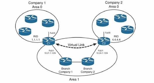 Two company have small office( branch )in the same city, after merging, add the link between branch office can be a cost-effective choice, it also creates a design problem: two backbone areas now exist, and OSPF requires that the backbone area be contiguous. To solve this problem, engineer configures a virtual link between ABRs C1 and C2. Thus, area 0 contiguous.
Verification
show ip ospf virtual-links
example
Router3.3.3.3#show ip ospf virtual-links

Virtual Link OSPF_VL3 to router 1.1.1.1 is up
  Run as demand circuit
  DoNotAge LSA allowed.
  Transit area 1, via interface ATM2/0.20, Cost of using 65
  Transmit Delay is 1 sec, State POINT_TO_POINT,
  Timer intervals configured, Hello 10, Dead 40, Wait 40, Retransmit 5
    Hello due in 00:00:01
    Adjacency State FULL (Hello suppressed)
    Index 1/2, retransmission queue length 0, number of retransmission 0
    First 0x0(0)/0x0(0) Next 0x0(0)/0x0(0)
    Last retransmission scan length is 0, maximum is 0
    Last retransmission scan time is 0 msec, maximum is 0 msec
- Assignment of a name to the virtual link, in example above is OSPF_VL3.
- Routers both allow the use of Do Not Age (DNA) bit, so periodic reflooding will not occur over this virtual link.
- Transit area number, area 1.
- The cost of the virtual link, 65.
- Adjacency state: Full.
show ip ospf neighbor
show ip ospf neighbor detail RID