TCP:
- TCP Maximum Segment Size (MSS) defines the largest amount of data that the receiving device is able to accept in a single TCP segment.
- To avoid fragmentation of an IPv4 packet, the selection of the TCP MSS is the minimum buffer size and MTU of the outgoing interface minus 40 bytes. The 40 bytes take into account the 20-byte IPv4 header and the 20-byte TCP header.
- The TCP MSS helps avoid fragmentation at the two ends of the TCP connection but it does not prevent fragmentation due to a smaller MTU on a link along the path.
- Path MTU Discovery (PMTUD) was developed for the purpose of determining the lowest MTU along a path from the packet’s source to destination.
- PMTUD is only supported by TCP.
- TCP can experience bottlenecks on paths with high bandwidth and long round-trip delays.
- These networks are known as a long fat pipe or long fat network , LFN (pronounced “elephan [t]).”
- The key parameter is the Bandwidth Delay Product (BDP), which is the product of the bandwidth (bps) times the round-trip delay (RTT in seconds).
- The BDP is the number of bits it takes to “fill the pipe” (in other words, the amount of unacknowledged data that TCP must handle to keep the pipeline full).
- BDP is used to optimize the TCP window size to fully utilize the link.
- The result is the maximum of data that can be transmitted on the link at any given time. The TCP window size should then use the BDP.
- The TCP window size indicates the amount of data that can be sent before expecting an acknowledgment, usually several times the MSS.
UDP
- However, UDP is a lightweight protocol for faster and simpler data transmissions and does not include these features.
- When there is a combination of TCP and UDP flows during a period of congestion, TCP tries to do its part by backing off on bandwidth, called slow start .
- TCP starvation/UDP dominance: UDP without any flow control mechanisms continues, potentially using up the available bandwidth given up by TCP.
- It is not always possible to separate TCP- and UDP-based flows, but it is important to be aware of this behavior when mixing applications that use both transport layer protocols.
End-to-end latency
- The flow control and reliability features of TCP have an effect on end-to-end latency.
- TCP requires an established virtual connection, and bidirectional communications for acknowledgments, window sizes, congestion control, and other TCP mechanisms, all of which has an effect on latency.
- UDP is a protocol that does not include reliability or flow control. A device simply sends packets with UDP segments with the assumption that they will reach their destination.
- UDP is typically used for applications such as streaming media that require minimal delay and can tolerate occasional packet loss. UDP has very low latency, better than most TCP connections.
ICMP redirect
- ICMPV4 Redirect messages are used by routers to notify the sender of a packet that there is a better route available for a particular destination.
An ICMP redirect is an error message sent by a router to the sender of an IP packet . Redirects are used when a router believes a packet is being routed sub optimally and it would like to inform the sending host that it should forward subsequent packets to that same destination through a different gateway. In theory a host with multiple gateways could have one default route and learn more optimal specific routes over time by way of ICMP redirects. Consider the following diagram.
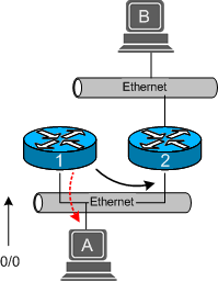
Figure 1 – ICMP Redirect from Router 1.
In Figure 1, host A wishes to send a packet to host B. The routing table on host A consists of a default route through router R1. When R1 receives a packet destined for host B, it looks at its routing table and notices that it has a route (not default) to R2 for packets destined to host B. Therefore, it forwards the datagram to R2, who in turn passes it along to host B. Router 1 also notices that the outgoing interface and network for the packet was the same as the interface it arrived on. Since it is configured to send ICMP redirects, it sends an error message to host A informing it that all packets destined for host B should be forwarded to R2.
It makes sense for router 1 to send a redirect because host A could have just as easily send packets through R2 to start with. Sending packets through R2 directly would decrease the number of routing hops for host A, and increase performance on R1’s link. Obviously redirects would not be involved if host A contained a static route to R2 for packets to host B, or if R1 could forward packets to host B through a better path such as a directly connected interface.
Before an ICMP redirect is generated, the following restrictions are typically adhered to on most of today’s routers:
- The outgoing and incoming interface of the packet must be the same.
- The IP source address in the packet is on the same logical IP network as the next-hop IP address.
- The route used for the outgoing packet must not be an ICMP redirect or a default route.
- The packet does not contain an IP source route option.
- The gateway must be configured to send redirects.
RFC 1122 [2] states that hosts should NOT send ICMP redirects. However, just as gateways follow a set of guidelines as to whether they will send redirects, hosts also have a built-in set of protections to prevent inadvertent additions to their routing table. The following checks are typically performed at the host, not all of which are listed in RFC 1122 before adding a redirect route to the routing table:
- The new router must be reachable through a directly connected network.
- The new route must be from the existing router for the destination in question.
- The new route cannot specify the host as the next-hop address.
- The redirect route must not point to an address on the local subnet.
- The host must be configured to accept redirects.
For more, see here: http://www.cymru.com/gillsr/documents/icmp-redirects-are-bad.htm
IPv6 review:
http://frankfu.click/networking/networking-fundamental/ipv4-vs-ipv6/2/
RIPng
Rip overview:
- Split horizon with poison reverse is a similar technique but sends the update with a metric of 16, which is considered unreachable by RIP.
- RIP is also capable of load balancing traffic over equal-cost paths.
- The default is four equal-cost paths.
- If the maximum number of paths is set to one, load balancing is disabled.
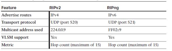 Big differences between RIPv2 and RIPng:
- RIPng does not use network command, use
ipv6 rip name enableinterface subcommand. - Cisco IOS does not route IPv6 by default ( if no
ipv6 unicast-routingcommand issued) - RIPng allows multiple RIPng processes on a single router.
Steps to configure RIPng:
Step1. Enable IPv6 routing with the ipv6 unicast-routing global command.
Step2. ENable RIPng using the ipv6 router rip name global configuration command.
+ name must be unique on a router but does not need to match on neighboring routers
Step3. Enable IPv6 on the interface, typically with one of these two methods:
+ configure the IPv6 unicast address on each interface using the ipv6 address address/prefix-length interface command.
+ configure the ipv6 enable command, which enables IPv6 and causes the router to derive its link-local address.
Step 4. Enable RIPng on the interface with the ipv6 rip name enable interface subcommand.
+ name maches the name in step2.
Explanation:
- Step 2 relies on step 1, because cisco IOS rejects the command at step2 if the command at step 1 has been omitted.
- Step 4 relies on step 3, because cisco IOS rejects the command at step4 if IPV6 has not yet been enabled on the interface.
- If you forgot step 2, and issued step 4, the IOS automatically create the command at step2. similar to the VLAN, if you assign a interface to a vlan without creating the vlan, the IOS create the vlan automatically.
Default route
On the interface connect to last resort, use ipv6 rip name default-information {originate | only} command.
- The originate keyword propagates the default route in addition to other routes in R1’s routing table.
- The Only keyword propagates the default route only in R1’s routing table.
Route Summary
- The same process for summarizing IPv4 networks is used for summarizing IPv6 prefixes.
Metrics
- The metric for RIPng routes in the routing table is shown as 2. In RIPng, the sending router already considers itself to be one hop away; therefore There is a significant difference in how RIPv2 and RIPng calculate the number of hops for a remote network. In RIPng, the routers adds one hop to the metric when it receives the RIPng update and then includes that metric in its IPv6 routing table for that network.
- In RIPv1 and RIPv2, the router receives the RIP update, uses that metric for its IPv4 routing table and then increments the metric by one before sending the update to other routers.
- The effect of all of this is that RIPng will show a metric, a hop count of one more than RIPv1 or RIPv2.
Verify the RIPng
similar to the rip, change the ip into ipv6.
show ipv6 rip database:
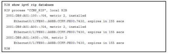
- Installed or expired, in which the keyword “installed” means the route is in the routing table. If a network becomes unavailable, the route will become “expired” after the dead timer expires. An expired route value (in seconds), during which the route will be advertised as expired, is listed.
- Expires in, in which if the countdown timer reaches 0, the route is removed from the routing table and marked expired. This timer, the dead timer, is by default three times the hello timer—180 seconds.