Entity Relationship Modeling
The ERD represents the conceptual database as viewed by the end user. ERDs depict the database’s main components: entities, attributes, and relationships.
Some conceptual database modeling concepts can be expressed only using the Chen notation.
- The Chen notation favors conceptual modeling.
- The Crow’s Foot notation favors a more implementation-oriented approach.
- The UML notation can be used for both conceptual and implementation modeling.
Entity
An entity is an object of interest to the end user.
In the Chen, Crow’s Foot, and UML notations, an entity is represented by a rectangle that contains the entity’s name. The entity name, a noun, is usually
written in all capital letters.
Attributes
Attributes are characteristics of entities.
Required and Optional Attributes
- A required attribute is an attribute that must have a value; in other words, it cannot be left empty.
- Optional attribute is an attribute that does not require a value, therefore, it can be left empty.
Domain is the set of possible values for a given attribute. Attributes may share a domain. For example a student and professor address share the same domain of all possible addresses.
Identifiers(primary keys): Entities are mapped to tables, and the entity identifier is mapped as the table’s primary key(PK). Key attributes are also underlined in a frequently used shorthand notation for the table structure, called a relational schema that uses the following format:
TABLE NAME(KEY_ATTRIBUTE1, ATTRIBUTE 2, ATTRIBUTE3, ... AttributeK)
The key_attribute1 is the primary key here.
E.G. a car entity may be represented by : car(car_vin, mod_code, car_year,car_color)
Composite identifier: A primary key composed of more than one attribute.
Composite and Simple attributes -according to the number of attribute
- A composite attribute is an attribute that can be further subdivided to yield additional attributes.
- A simple attribute can not be subdivided.
According to the number of value for attribute(s)
- Single valued attributes: an attribute that can have only single value. Keep in mind that a single-valued attribute is not necessarily a simple attribute.
- Multi valued attributes are attributes that can have may values.
Note, Actually, proper use of database modeling software will automatically produce the FK when the relationship is defined. In addition, the software will label the FK appropriately and write the FK’s implementation details in a data dictionary. Therefore, when you use professional database modeling software, never type the FK attribute yourself.
Derived Attributes
A derived attribute is an attribute whose value is calculated from other attributes. The derived attribute need not be physically stored within the database, it can be derived by using an algorithm.
A derived attribute is indicated in the Chen notation by a dashed line that connects the attribute and the entity. The Crow’s Foot notation does not have a method for distinguishing the derived attribute from other attributes. So derived attributes are sometimes referred as computed attributes.
Relationships
Relationship is an association between entities, the entities that participate in a relationship are known as participants.
Relationships between entities always operate in both directions. The relationship between participants can be 1:M, 1:1, N:M.
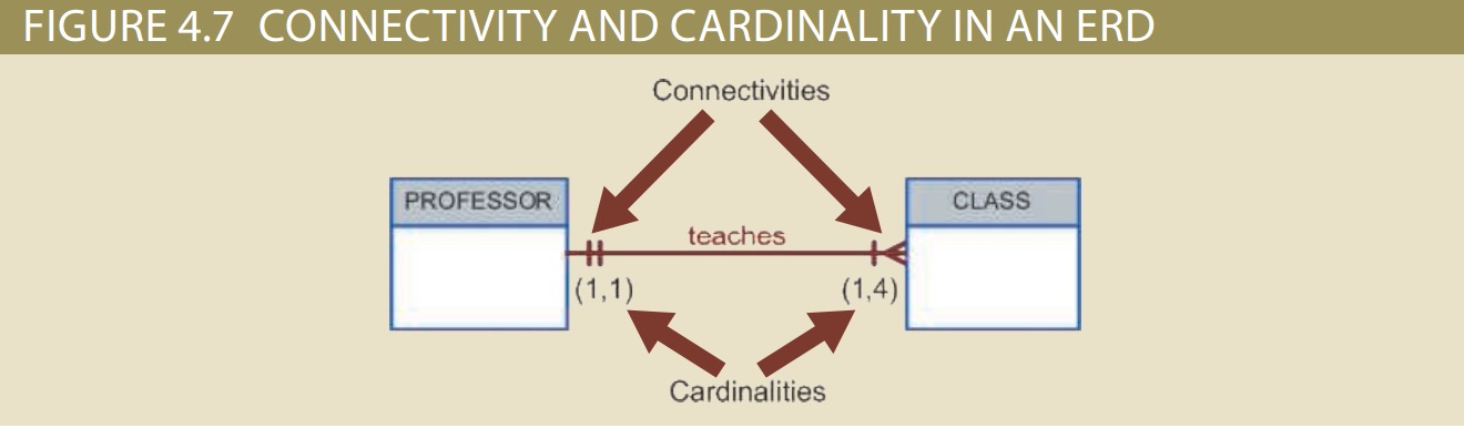
Connectivity and Cardinality
Connectivity is used to describe the relationship classification.
Cardinality expresses the minimum and maximum number of entity occurrences associated with one occurrence of the related entity.
Connectivities and cardinalities are established by concise statements known as business rules.
The format (x,y) the first value represents the minimum number of associated entities, second value represents the maximum number of associated entities.
E.g.
Keep in mind that the DBMS can not handle the implementation of the cardinalities at the table level-the capability is provided by the application software or by triggers.
In Figure 4.7, the cardinality (1,4) next the class entity indicates that each professor teachers up to 4 classes, which means that the Professor table’s primary key value occurs at least once and more than four times as foreign key values in the CLASS table. The cardinality (1,1) next to the professor entity indicates that each class is taught by one and only one professor.
If the cardinality has been written as (1,N) next the class entity, there would be no upper limit to the number of classes a professor might tech.
Existence Dependence
An entity is said to be existence-dependent if it can exist in the database only when it is associated with another related entity occurrence. In other word, an entity is existence-dependent if it has a mandatory foreign key and the foreign key attribute that can not be null.
Strong Entity: If an entity can exist apart from all of its related entities, then it is existence-idependent, and it is referred to as a strong entity or regular entity.
Weak entity
a weak entity is one that meets two conditions:
1. The entity is existence-dependent; it cannot exist without the entity with which it has a relationship.
2. The entity has a primary key that is partially or totally derived from the parent entity in the relationship.
the Chen notation in Figure 4.10 identifies the weak entity by using a double-walled entity rectangle. The Crow’s Foot notation generated by Visio Professional uses the relationship line and the PK/FK designation to indicate whether the related entity is weak. A strong (identifying) relationship indicates that the related entity is weak.
The weak entity inherits part of its primary key from its strong counterpart.
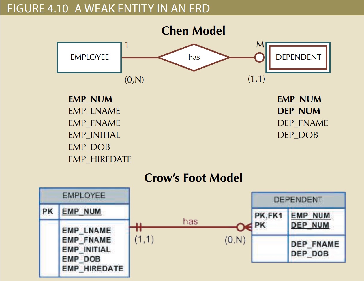
An EMPLOYEE might or might not have a DEPENDENT, but the DEPENDENT must be associated with an EMPLOYEE. Moreover, the DEPENDENT cannot exist without the EMPLOYEE; that is, a person cannot get insurance coverage as a dependent unless the person is a dependent of an employee. DEPENDENT is the weak entity in the relationship “EMPLOYEE has DEPENDENT.”
Relationship strength
The concept of relationship strength is based on how the primary key of a related entity is defined. To implement a relationship, the primary key of one entity (the parent entity, normally on the “one” side of the one-to-many relationship) appears as a foreign key in the related entity (the child entity, mostly the entity on the “many” side of the oneto-many relationship).
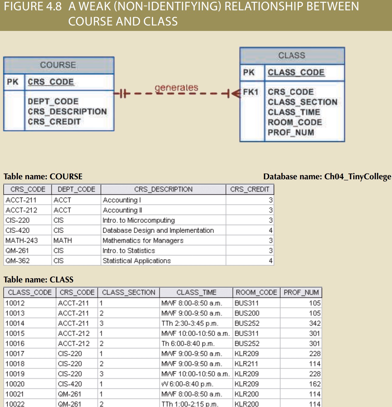
Weak(Non-identifying) relationship: also known as a non-identifying relationship, exists if the primary key of the related entity does not contain a primary key component of the parent entity.
By default, relationships are established by having the primary key of the parent entity appear as a foreign key (FK) on the related entity (also known as the child entity)
E.g.
COURSE (CRS_CODE, DEPT_CODE, CRS_DESCRIPTION, CRS_CREDIT)
CLASS (CLASS_CODE, CRS_CODE, CLASS_SECTION, CLASS_TIME,ROOM_CODE, PROF_NUM)
In this case, a weak relationship exists between COURSE and CLASS because CRS_CODE (the primary key of the parent entity) is only a foreign key in the CLASS entity. In this example, the CLASS primary key did not inherit a primary key component from the COURSE entity. The Crow’s Foot notation depicts a weak relationship by placing a dashed relationship line between the entities.
Strong(identifying) Relationships
A strong relationship exists when the primary key of the related entity contains a primary key component of the parent entity.
For example, suppose the 1:M relationship between COURSE and CLASS is defined as:
COURSE (CRS_CODE, DEPT_CODE, CRS_DESCRIPTION, CRS_CREDIT)
CLASS (CRS_CODE, CLASS_SECTION, CLASS_TIME, ROOM_CODE, PROF_NUM)
The Crow’s Foot notation depicts the strong (identifying) relationship with a solid line between the entities.
Note that The nature of the relationship is often determined by the database designer.
Keep in mind that the order in which the tables are created and loaded is very important. you must load the data of the “1” side first in a 1:M relationship to avoid the possibility of referential integrity errors, regardless of whether the relationships are weak or strong.
Weak entity in a strong relationship
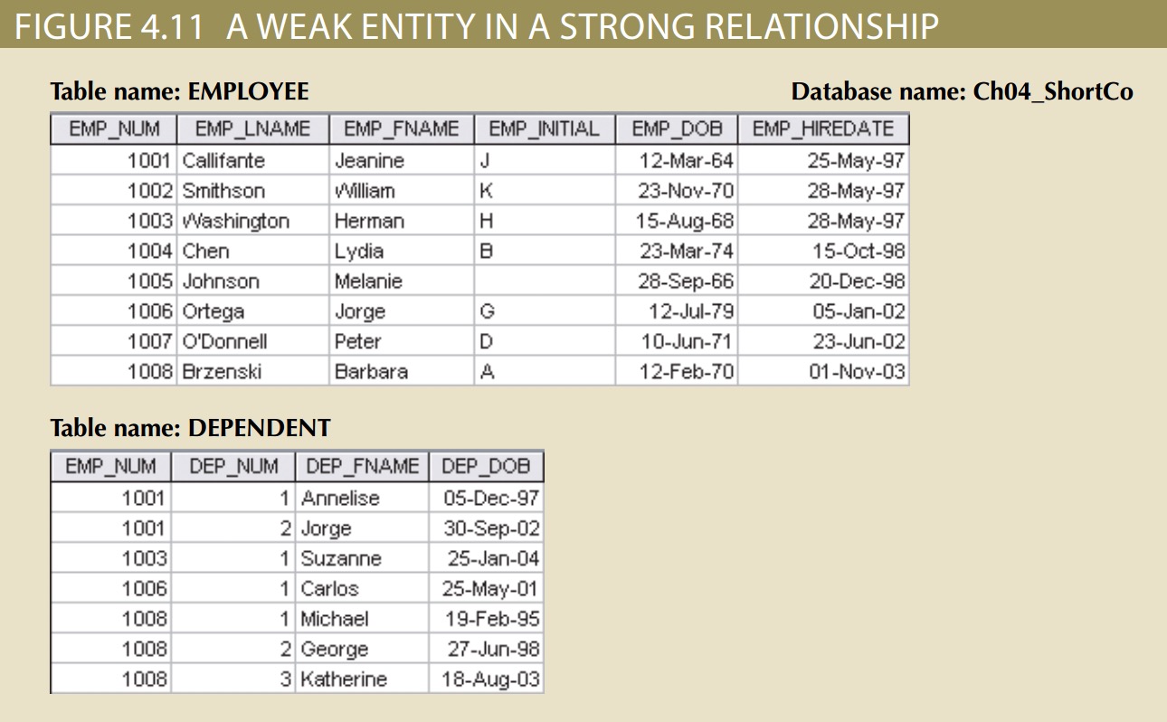
Figure 4.11 illustrates the implementation of the relationship between the weak entity (DEPENDENT) and its parent or strong counterpart (EMPLOYEE). Note that DEPENDENT’s primary key is composed of two attributes, EMP_NUM and DEP_NUM, and that EMP_NUM was inherited from EMPLOYEE.
Keep in mind that the database designer usually determines whether an entity can be described as weak based on the business rules.
Relationship Participation
The participation in an entity relationship is either optional or mandatory.
Optional participation means that one entity occurrence does not require a corresponding entity occurrence in a particular relationship. E.g. in the “course generates class” relationship, some courses do not generate a class.
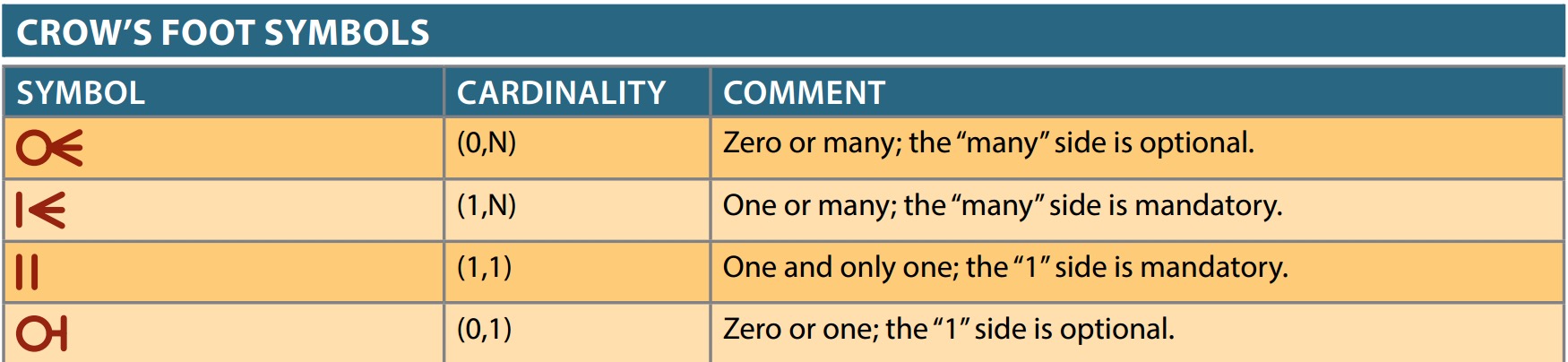
In Crow’s Foot notation, an optional relationship between entities is shown by drawing a small circle( O ) on the side of the optional entity. In other words the existence of an optional entity indicates that its minimum cardinality is 0.
The burden of establishing the relationship is always placed on the entity that contains the foreign key. In most cases, the entity is on the “many” side of the relationship.
Mandatory participation means that one entity occurrence requires a corresponding entity occurrence in a particular relationship. The mandatory participation is shown as a small hash mark across the relationship line(||). The existence of a mandatory relationship indicates that the minimum
cardinality is at least 1 for the mandatory entity.
Relationship Degree
A relationship degree indicates the number of entities or participants associated with a relationship. A unary relationship exists when an association is maintained within a single entity. A binary relationship exists when two entities are associated. A ternary relationship exists when three entities are associated.
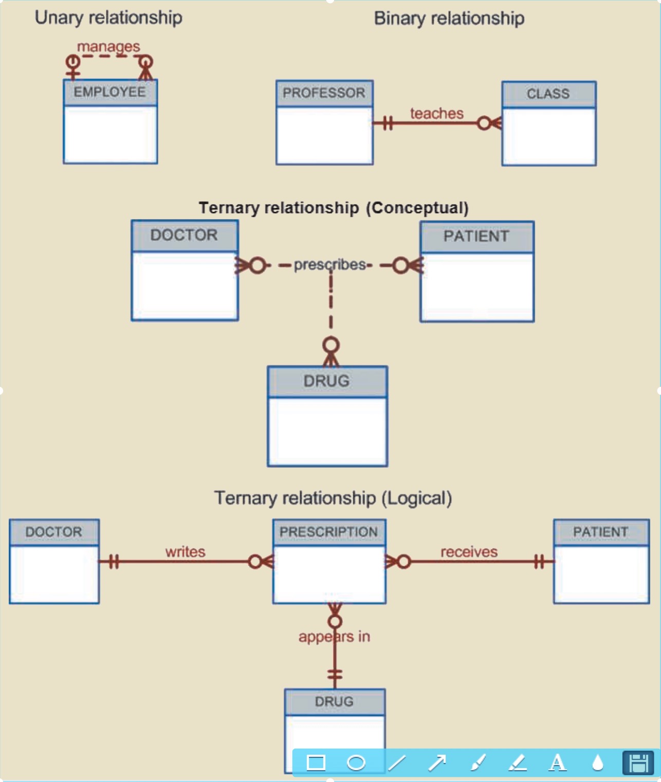
- Unary Relationships: As shown in the graph, an employee within the EMPLOYEE entity is the manager for one or more employees within that entity. The “manage”relationship means that EMPLOYEE requires another EMPLOYEE to be the manager –that is EMPLOYEE has a relationship with itself. Such a relationship is known as a recursive relationship.
- Binary Relationships: This is the most common type of relationship, which means two entities are associated in a relationship.
- Ternary and higher-order relationships: A ternary relationship implies an association among three different entities.
Recursive Relationship
A recursive relationship is one in which a relationship can exist between occurrences of the same entity set.
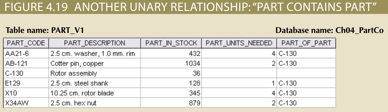
Unary relationships are common in manufacturing industries.
E.g. Figure4.19 illustrates that a rotor assembly (C-130) is composed of many parts, but each part is used to create only one rotor assembly.
Referential integrity deals with the correspondence of values in the foreign key with values in the related primary key. Referential integrity is not bidirectional.
Associative(composite) Entities
In practical terms, both participation and referential integrity involve the values used as primary keys and foreign keys to implement the relationship. This associative entity, also called a composite or bridge entity, is in a 1:M relationship with the parent entities and is composed of the primary key attributes of each parent entity. Furthermore, the associative entity can have additional attributes of its own. When using the Crow’s Foot notation, the associative entity is identified as a strong (identifying) relationship, as indicated by the solid relationship lines between the parents and the associative entity.
Develop an ERD
Building an ERD usually involves the following activities:
- Create a detailed narrative of the organisation’s description of operations.
- Identify the business rules based on the description of operations.
- Identify the main entities and relationships from the business rules.
- Develop the initial ERD.
- Identify the attributes and primary keys that adequately describe the entities.
- Revise and review the ERD.