Modern cable systems provide two-way communication between subscribers and the cable operator. Cable operators now offer customers advanced telecommunications services, including high-speed Internet access, digital cable television, and residential telephone service. Cable operators typically deploy hybrid fiber-coaxial (HFC) networks to enable high-speed transmission of data to cable modems located in a SOHO.
Compare broadband
Cable system
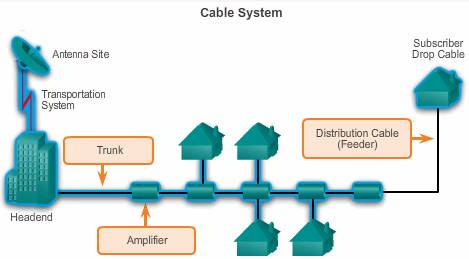
- Antenna Site
The location of an antenna site is chosen for optimum reception of over-the-air, satellite, and sometimes point-to-point signals. The main receiving antennas and satellite dishes are located at the antenna site. - Transportation System
A transportation network links a remote antenna site to a headend or a remote headend to the distribution network. The transportation network can be microwave, coaxial supertrunk, or fiber optic. - Headend
This is where signals are first received, processed, formatted, and then distributed downstream to the cable network. The headend facility is usually unmanned, under security fencing, and is similar to a telephone company central office. - Amplifier
In a classic cable system called a tree-and-branch cable system, the distribution network consists of trunk and feeder cables. The trunk is the backbone that distributes signals throughout the community service area to the feeder and typically uses 0.750 inch (19 mm) diameter coaxial cable. The feeder branches flow from a trunk and reach all of the subscribers in the service area via coaxial cables. The feeder cable is usually a 0.50 inch (13 mm) diameter coaxial cable. - Subscriber Drop cable
A subscriber drop connects the subscriber to the cable services. The subscriber drop is a connection between the feeder part of a distribution network and the subscriber terminal device (for example, TV set, Blu-ray players, High Definition TV set-top box, or cable modem). A subscriber drop consists of radio grade (RG) coaxial cabling (usually 59-series or 6-series coaxial cable), grounding and attachment hardware, passive devices, and a set-top box.
A cable network is capable of transmitting signals on the cable in either direction at the same time. The following frequency scopes are used:
- Downstream – The direction of an RF signal transmission, such as TV channels and data, from the source, or headend, to the destination, or subscribers. Transmission from source to destination is called the forward path. Downstream frequencies are in the range of 50 to 860 MHz.
- Upstream – The direction of the RF signal transmission from subscribers to the headend. Upstream frequencies are in the range of 5 to 42 MHz.
Cable Electromagnetic spectrum
 DOCSIS
The Data-over-Cable Service Interface Specification (DOCSIS) is an international standard developed by CableLabs, a non-profit research and development consortium for cable-related technologies. CableLabs tests and certifies cable equipment vendor devices, such as cable modems and cable modem termination systems, and grants DOCSIS-certified or qualified status.
Cable operators employ DOCSIS to provide Internet access over their existing HFC infrastructure
DOCSIS specifies the OSI Layer 1 and Layer 2 requirements:
- Physical layer – For data signals that the cable operator can use, DOCSIS specifies the channel widths, or bandwidths of each channel, as 200 kHz, 400 kHz, 800 kHz, 1.6 MHz, 3.2 MHz, and 6.4 MHz. DOCSIS also specifies modulation technique, which is how to use the RF signal to convey digital data.
- MAC layer – Defines a deterministic access method, Time-Division Multiple Access (TDMA), or Synchronous Code Division Multiple Access method (S-CDMA).
To understand the MAC layer requirements for DOCSIS, an explanation of how various communication technologies divide channel access is helpful.
- TDMA divides access by time.
- Frequency-Division Multiple Access (FDMA) divides access by frequency.
- Code Division Multiple Access (CDMA) employs spread-spectrum technology and a special coding scheme in which each transmitter is assigned a specific code.
An analogy that illustrates these concepts starts with a room representing a channel. The room is full of people needing to speak to one another. In other words, each person needs channel access. One solution is for the people to take turns speaking (time division). Another is for each person to speak at different pitches (frequency division).
S-CDMA is a proprietary version of CDMA developed by Terayon Corporation for data transmission across coaxial cable networks. S-CDMA scatters digital data up and down a wide frequency band and allows multiple subscribers connected to the network to transmit and receive concurrently. S-CDMA is secure and extremely resistant to noise.
Plans for frequency allocation bands differ between North American and European cable systems. Euro-DOCSIS is adapted for use in Europe. The main differences between DOCSIS and Euro-DOCSIS relate to channel bandwidths. TV technical standards vary across the world, which affects the way DOCSIS variants develop. International TV standards include NTSC in North American and parts of Japan; PAL in most of Europe, Asia, Africa, Australia, Brazil, and Argentina; and SECAM in France and some Eastern European countries.
Cable components
Two types of equipment are required to send digital modem signals upstream and downstream on a cable system:
- Cable Modem Termination System (CMTS) at the headend of the cable operator
- Cable Modem (CM) on the subscriber end
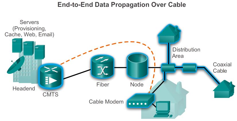
- CMTS: A cable modem termination system (CMTS) is a component that exchanges digital signals with cable modems on a cable network. A headend CMTS communicates with CMs that are located in subscriber homes.
- Fiber: The trunk portion of the cable network is usually fiber optic cable.
- Nodes: Nodes convert optical signals to RF signals.
- Distributions Area: A distribution network segment (feeder segment) is from 500 to as many as 2000 subscribers.
- Coaxial cable: Coaxial feeder cables originate from the node and carry RF signals to the subscribers.
- Cable Modem: A cable modem enables you to receive data at high speeds. Typically, the cable modem attaches to a standard 10BASE-T Ethernet card in the computer.
A headend CMTS communicates with CMs located in subscriber homes. The headend is actually a router with databases for providing Internet services to cable subscribers. The architecture is relatively simple, using a mixed optical-coaxial network in which optical fiber replaces the lower bandwidth coaxial cable.
A web of fiber trunk cables connects the headend to the nodes where optical-to-RF signal conversion takes place. The fiber carries the same broadband content for Internet connections, telephone service, and streaming video as the coaxial cable carries.
Coaxial feeder cables originate connect the node to the subscribers and carries RF signals.
The actual bandwidth for Internet service over a CATV line can be up to 160 Mb/s downstream with the latest iteration of DOCSIS, and up to 120 Mb/s upstream.
When high usage causes congestion, the cable operator can add additional bandwidth for data services by allocating an additional TV channel for high-speed data. This addition may effectively double the downstream bandwidth that is available to subscribers. Another option is to reduce the number of subscribers served by each network segment. To reduce the number of subscribers, the cable operator further subdivides the network by laying the fiber-optic connections deeper into the neighborhoods.
DSL
DSL connection
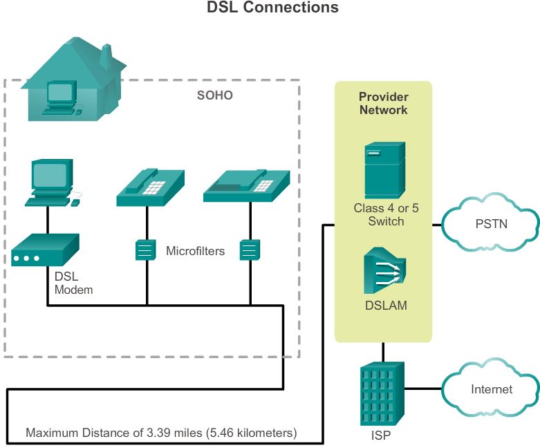
Service providers deploy DSL connections in the last step of a local telephone network, called the local loop or last mile. The connection is set up between a pair of modems on either end of a copper wire that extends between the customer premises equipment (CPE) and the DSL access multiplexer (DSLAM).
A DSLAM is the device located at the Central Office (CO) of the provider and concentrates connections from multiple DSL subscribers. A DSLAM is often built into an aggregation router.
 PSTN: public switched telephone network
Figure shows the equipment needed to provide a DSL connection to a SOHO. The two components are the DSL transceiver and the DSLAM:
- Transceiver – Connects the computer of the teleworker to the DSL. Usually the transceiver is a DSL modem connected to the computer using a USB or Ethernet cable. Newer DSL transceivers can be built into small routers with multiple 10/100 switch ports suitable for home office use.
- DSLAM – Located at the CO of the carrier, the DSLAM combines individual DSL connections from users into one high-capacity link to an ISP, and therefore, to the Internet.
The major benefit of ADSL is the ability to provide data services along with POTS voice services. Transmissions of voice and data signals are propagated along the same wire pair. Data circuits are offloaded from the voice switch.
Note that the maximum distance of 5.46 kilometers between the transceiver and DSLAM, so if you live in the blind spot of the ISP DSLAM, you will not have internet access to via this ISP.
There are two ways to separate ADSL from voice at the customer premises: using a microfilter or using a splitter.
- A microfilter is a passive low-pass filter with two ends, as shown in Figure bellow. One end connects to the telephone, and the other end connects to the telephone wall jack. This solution allows the user to use any jack in the house for voice or ADSL service.

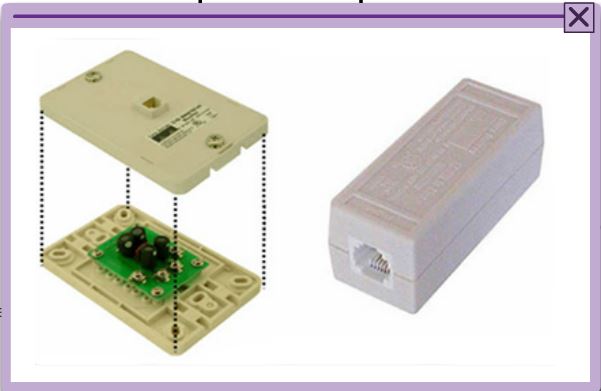
- When the service provider puts analog voice and ADSL on the same wire pair, ADSL signals can distort voice transmission. For this reason, the provider splits the POTS channel from the ADSL modem at the customer premises using filters or splitters. This setup guarantees uninterrupted regular phone service even if ADSL fails.
A POTS splitter separates the DSL traffic from the POTS traffic. The POTS splitter is a passive device. Figure bellow shows a diagram of a splitter.

In the event of a power failure, the voice traffic still travels to the voice switch in the CO of the carrier. Splitters are located at the CO and, in some deployments, at the customer premises. At the CO, the POTS splitter separates the voice traffic, destined for POTS connections, and the data traffic destined for the DSLAM. Installing the POTS splitter at the NID usually means that a technician must go to the customer site.
The actual device that marks the demarcation point is the Network Interface Device (NID). At this point, a splitter can be attached to the phone line. The splitter forks the phone line; one branch provides the original house telephone wiring for telephones, and the other branch connects to the ADSL modem. The splitter acts as a low-pass filter, allowing only the 0 to 4 kHz frequencies to pass to or from the telephone.
Wireless
For more wireless, see here.
Developments in broadband wireless technology are increasing wireless availability. These broadband types are explained in Figure 1 and include:
- Municipal Wi-Fi (Mesh)
- WiMAX (Worldwide Interoperability for Microwave Access)
- Cellular/mobile
- Satellite Internet
A company can create a private WAN using satellite communications and Very Small Aperture Terminals (VSAT). A VSAT is a type of satellite dish similar to the ones used for satellite TV from the home and is usually about 1 meter in width. The VSAT dish sits outside, pointed at a specific satellite, and is cabled to a special router interface, with the router inside the building. Using VSATs creates a private WAN.
XDSL Configuration
PPPoE
A commonly used data link layer protocol by ISPs is the Point-to-Point Protocol (PPP). PPP can be used on all serial links including those links created with dial-up analog and ISDN modems. To this day, the link from a dialup user to an ISP, using analog modems, likely uses PPP.
Additionally, ISPs often use PPP as the data link protocol over broadband connections.
There are several reasons for this.
- First, PPP supports the ability to assign IP addresses to remote ends of a PPP link. With PPP enabled, ISPs can use PPP to assign each customer one public IPv4 address.
- More importantly, PPP supports CHAP authentication. ISPs often want to use CHAP to authenticate customers because during authentication, ISPs can check accounting records to determine whether the customer’s bill is paid, prior to letting the customer connect to the Internet.
These technologies came to market in the following order, with varying support for PPP:
1. Analog modems for dialup that could use PPP and CHAP
2. ISDN for dialup that could use PPP and CHAP
3. DSL, which did not create a point-to-point link and could not support PPP and CHAP
ISPs value PPP because of the authentication, accounting, and link management features. Customers appreciate the ease and availability of the Ethernet connection.
However, Ethernet links do not natively support PPP. A solution to this problem was created, PPP over Ethernet (PPPoE).
Configure PPPoE
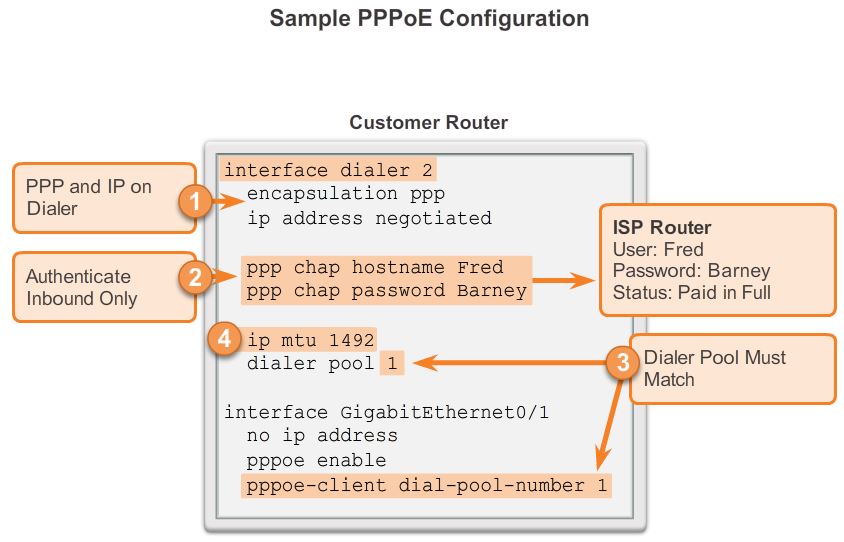
1. To create a PPP tunnel, the configuration uses a dialer interface. A dialer interface is a virtual interface. The PPP configuration is placed on the dialer interface, not the physical interface. The dialer interface is created using the interface dialer number command. The client can configure a static IP address, but will more likely be automatically assigned a public IP address by the ISP.
2. The PPP CHAP configuration usually defines one-way authentication– the ISP authenticates the customer. The hostname and password configured on the customer router must match the hostname and password configured on the ISP router.
3. The physical Ethernet interface that connects to the DSL modem is then enabled with the command pppoe enable that enables PPPoE and links the physical interface to the dialer interface. The dialer interface is linked to the Ethernet interface with the dialer pool and pppoe-client dial-pool-number commands, using the same number. The dialer interface number does not have to match the dialer pool number.
4. The maximum transmission unit (MTU) should be set down to 1492, versus the default of 1500, to accommodate the PPPoE headers.
Configuration example:
Internal Ethernet interface configuration
interface FastEthernet 0/1
description internal interface
ip address 10.1.1.1 255.255.255.0
ip nat inside
no shut
We have configure an IP address on the internal interface and specified it as the Inside NAT interface
External Ethernet interface configuration
Interface FastEthernet 0/0

 Description DSL interface

 no ip address

 pppoe enable

 pppoe-client dial-pool-number 1

 no shut
We have enabled PPPoE on the interface connected to the ISP and associated a dialer interface with it.
Dialer interface configuration
interface Dialer1

 ip address negotiated

 ip mtu 1492

 ip nat outside

 encapsulation ppp

 dialer pool 1

 ppp authentication chap pap callin

 ppp pap sent-username USERNAME password P@ssw0rd

 ppp chap hostname HOSTNAME

 ppp chap password P@ssw0rd

 no shut
Dialer Interface configuration includes PPP negotiation and authentication information.
Configuring Access List
ip access-list extended NAT_ACL 100 permit ip 10.10.10.0 0.0.0.255 any
This access-list matches traffic that should be translated to the Dialer Interface IP address for Internet access
NAT/PAT configuration
ip nat inside source list NAT_ACL interface dialer 1 overload
NAT configuration for translating traffic matched in the above ACL to Dialer Interface IP address
DHCP server services configuration
ip dhcp pool LAN_DHCP
network 10.1.1.0 /24
dns-server 4.2.2.2
default-router 10.1.1.1
DHCP Server Configuration for assigning the IP address and other parameters to LAN users
Static default route configuration
ip route 0.0.0.0 0.0.0.0 dialer 1
Finally a static default route is added that points towards the Dialer Interface.
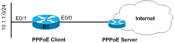
How to set up PPPOE server simulation and PPPOE client:
Trouble shooting and verifying:
show ip interface brief
debug ppp negotiation