The data link layer is actually divided into two sublayers:
- Logical Link Control (LLC): This upper sublayer defines the software processes that provide services to the network layer protocols. It places information in the frame that identifies which network layer protocol is being used for the frame. This information allows multiple Layer 3 protocols, such as IPv4 and IPv6, to utilize the same network interface and media.
- Media Access Control (MAC): This lower sublayer defines the media access processes performed by the hardware. It provides data link layer addressing and delimiting of data according to the physical signaling requirements of the medium and the type of data link layer protocol in use. The technique used for getting the frame on and off media is called the media access control method.
Separating the data link layer into sublayers allows for one type of frame defined by the upper layer to access different types of media defined by the lower layer.
Data link layer frame includes:
There is no one frame structure that meets the needs of all data transportation across all types of media. Depending on the environment, the amount of control information needed in the frame varies to match the media access control requirements of the media and logical topology. Although there are many different data link layer protocols that describe data link frames, basic parts: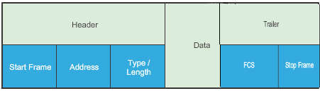
- Header: Contains control information, such as addressing, and is located at the beginning of the PDU.
- Data: Contains the IP header, transport layer header, and application data.
- Trailer: Contains control information for error detection added to the end of the PDU.
- A transmitting node creates a logical summary of the contents of the frame. This is known as the cyclic redundancy check (CRC) value. This value is placed in the Frame Check Sequence (FCS) field. When the frame arrives at the destination node, the receiving node calculates its own logical summary, or CRC, of the frame. The receiving node compares the two CRC values. If the two values are the same, the frame is considered to have arrived as transmitted. If the CRC value in the FCS differs from the CRC calculated at the receiving node, the frame is discarded.
There is always the small possibility that a frame with a good CRC result is actually corrupt. Errors in bits may cancel each other out when the CRC is calculated. Upper layer protocols would then be required to detect and correct this data loss. - Stop Frame, also called the Frame Trailer, is an optional field that is used when the length of the frame is not specified in the Type/Length field. It indicates the end of the frame when transmitted.
- A transmitting node creates a logical summary of the contents of the frame. This is known as the cyclic redundancy check (CRC) value. This value is placed in the Frame Check Sequence (FCS) field. When the frame arrives at the destination node, the receiving node calculates its own logical summary, or CRC, of the frame. The receiving node compares the two CRC values. If the two values are the same, the frame is considered to have arrived as transmitted. If the CRC value in the FCS differs from the CRC calculated at the receiving node, the frame is discarded.
Detail:
- Frame start and stop indicator flags: Used by the MAC sublayer to identify the beginning and end limits of the frame.
- Addressing: Used by the MAC sublayer to identify the source and destination nodes.
- Type: Used by the LLC to identify the Layer 3 protocol.
- Control: Identifies special flow control services.
-
- Priority/Quality of Service field: Indicates a particular type of communication service for processing.
- Logical connection control field: Used to establish a logical connection between nodes.
- Physical link control field: Used to establish the media link.
- Flow control field: Used to start and stop traffic over the media.
- Congestion control field: Indicates congestion in the media.
- Data: Contains the frame payload (i.e., packet header, segment header, and the data).
- Error Detection: Included after the data to form the trailer, these frame fields are used for error detection.
Ethernet Frame
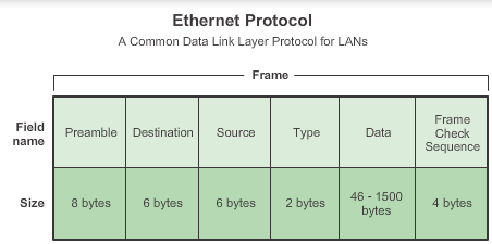
- Preamble: 7 bytes preamble consists of seven bytes all of the form 10101010, and is used by the receiver to allow it to establish bit synchronisation; 1 bytes delimiter is 10101011, which is a frame flag, indicating the start of a frame.
- Destination,Source: 48-bit( 6bytes) MAC address.
- Type: Value to indicate which upper layer protocol will receive the data after the Ethernet process is complete.
- Data or payload: If the data field is shorter than 46 bytes, it must be compensated by the Pad field. The reason for specifying a minimum length lies with the collision-detect mechanism. In CSMA/CD (carrier sense multiple access/collision detect) a station must never be allowed to believe it has transmitted a frame successfully if that frame has, in fact, experienced a collision.For more see here.
Point-to-Point Protocol
Another data link layer protocol is the Point-to-Point Protocol (PPP). PPP is a protocol used to deliver frames between two nodes. Unlike many data link layer protocols that are defined by electrical engineering organizations, the PPP standard is defined by RFCs.
PPP uses a layered architecture. To accommodate the different types of media, PPP establishes logical connections, called sessions, between two nodes. The PPP session hides the underlying physical media from the upper PPP protocol. These sessions also provide PPP with a method for encapsulating multiple protocols over a point-to-point link. Each protocol encapsulated over the link establishes its own PPP session.
PPP also allows the two nodes to negotiate options within the PPP session. This includes authentication, compression, and multilink (the use of multiple physical connections)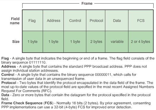
802.11 wireless frame
The IEEE 802.11 standard uses the same 802.2 LLC and 48-bit addressing scheme as other 802 LANs.
There are many differences at the MAC sublayer and physical layer. In a wireless environment, the environment requires special considerations. There is no definable physical connectivity; therefore, external factors may interfere with data transfer and it is difficult to control access. To meet these challenges, wireless standards have additional controls.
Wireless is contention-based system using a CSMA/CA media access process. CSMA/CA specifies a random backoff procedure for all nodes that are waiting to transmit. The most likely opportunity for medium contention is just after the medium becomes available. Making the nodes back off for a random period greatly reduces the likelihood of a collision.
Other services supported by 802.11 are authentication, association (connectivity to a wireless device), and privacy (encryption).
- Protocol Version field: Version of 802.11 frame in use
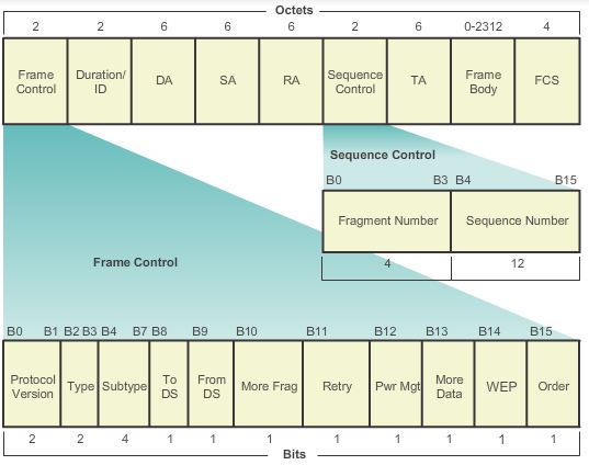
- Type and Subtype fields: Identifies one of three functions and sub functions of the frame: control, data, and management
- To DS field: Set to 1 in data frames destined for the distribution system (devices in the wireless structure)
- From DS field: Set to 1 in data frames exiting the distribution system
- More Fragments field: Set to 1 for frames that have another fragment
- Retry field: Set to 1 if the frame is a retransmission of an earlier frame
- Power Management field: Set to 1 to indicate that a node will be in power-save mode
- More Data field: Set to 1 to indicate to a node in power-save mode that more frames are buffered for that node
- Wired Equivalent Privacy (WEP) field: Set to 1 if the frame contains WEP encrypted information for security
- Order field: Set to 1 in a data type frame that uses Strictly Ordered service class (does not need reordering)
- Duration/ID field: Depending on the type of frame, represents either the time, in microseconds, required to transmit the frame or an association identity (AID) for the station that transmitted the frame
- Destination Address (DA) field: MAC address of the final destination node in the network
- Source Address (SA) field: MAC address of the node that initiated the frame
- Receiver Address (RA) field: MAC address that identifies the wireless device that is the immediate recipient of the frame
- Fragment Number field: Indicates the number for each fragment of a frame
- Sequence Number field: Indicates the sequence number assigned to the frame; retransmitted frames are identified by duplicate sequence numbers
- Transmitter Address (TA) field: MAC address that identifies the wireless device that transmitted the frame
- Frame Body field: Contains the information being transported; for data frames, typically an IP packet
- FCS field: Contains a 32-bit cyclic redundancy check (CRC) of the frame
Media access control
Topology:
- Physical topology: What people see. Refers to the physical connections and identifies how end devices and infrastructure devices such as routers, switches, and wireless access points are interconnected.
- Logical topology: What data see. Refers to the way a network transfers frames from one node to the next. This arrangement consists of virtual connections between the nodes of a network.Two basic media access control methods for shared media:
- Contention-based access: All nodes compete for the use of the medium but have a plan if there are collisions. Figure 1 shows contention-based access.
- Controlled access: Each node has its own time to use the medium.
WANs topologies:
WANs are commonly interconnected using the following physical topologies:
- Point-to-Point: This is the simplest topology which consists of a permanent link between two endpoints. For this reason, this is a very popular WAN topology.
- Physical point-to-point topologies directly connect two nodes, In this arrangement, two nodes do not have to share the media with other hosts.
- A virtual circuit is a logical connection created within a network between two network devices. The two nodes on either end of the virtual circuit exchange the frames with each other. Media access method used by the data link protocol is determined by the logical point-to-point topology, not the physical topology.
- Hub and Spoke: A WAN version of the star topology in which a central site interconnects branch sites using point-to-point links.
- Mesh: This topology provides high availability, but requires that every end system be interconnected to every other system. Therefore the administrative and physical costs can be significant.
LAN topologies: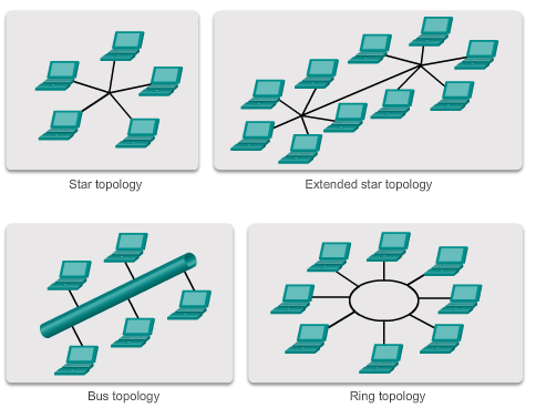
- Star: End devices are connected to a central intermediate device. Early star topologies interconnected end devices using hubs. However, star topologies now use switches. The star topology is the most common physical LAN topology primarily because it is easy to install, very scalable (easy to add and remove end devices), and easy to troubleshoot.
- Extended star or hybrid: In an extended star topology, central intermediate devices interconnect other star topologies. In a hybrid topology, the star networks may interconnect using a bus topology.
- Bus: All end systems are chained to each other and terminated in some form on each end. Infrastructure devices such as switches are not required to interconnect the end devices. Bus topologies were used in legacy Ethernet networks because it was inexpensive to use and easy to set up.
- Ring: End systems are connected to their respective neighbor forming a ring. Unlike the bus topology, the ring does not need to be terminated. Ring topologies were used in legacy Fiber Distributed Data Interface (FDDI) networks.
FDDIFiber Distributed Data Interface (FDDI) is a standard for data transmission in a local area network. It uses optical fiber as its standard underlying physical medium, although it was also later specified to use copper cable, in which case it may be called CDDI (Copper Distributed Data Interface), standardized as TP-PMD (Twisted-Pair Physical Medium-Dependent), also referred to as TP-DDI (Twisted-Pair Distributed Data Interface).