Two sublayer:
LLC(Logical Link Control) and MAC(Media Access Control)
- LLC: Specified in IEEE 802.2 standards.It’s job is to communicate with the upper layers of the application, and transition the packet to the lower layers for delivery.LLC is implemented in software, and its implementation is independent of the hardware. In a computer, the LLC can be considered the driver software for the NIC.
- MAC: MAC is implemented by hardware, typically in the computer NIC. The specifics are specified in the IEEE 802.3 standards.It has two responsibilities:
- Data encapsulation: Includes frame assembly before transmission and frame disassembly upon reception. In forming the frame, the MAC layer adds a header and trailer to the network layer PDU. Data encapsulation provides 3 functions:
- Frame delimiting: Provides important delimiters that are used to identify a group of bits that make up a frame. This process provides synchronization between the transmitting and receiving nodes.
- Addressing:Ethernet header contains the physical address(MAC address).
- Error detection: The trailer with a cyclic redundancy check (CRC) of the frame contents.
- Media Access Control: is responsible for placement of frames on the media and the removal of frames from the media.Ethernet is a contention-based method of networking. Recall that a contention-based method, or non-deterministic method, means that any device can try to transmit data across the shared medium whenever it has data to send. Ethernet provides a method for controlling how the nodes share access through the use a Carrier Sense Multiple Access (CSMA) technology.
- Data encapsulation: Includes frame assembly before transmission and frame disassembly upon reception. In forming the frame, the MAC layer adds a header and trailer to the network layer PDU. Data encapsulation provides 3 functions:
Collision:
If no carrier signal is detected, the device transmits its data. It is possible that the CSMA process will fail and two devices will transmit at the same time.This is called a data collision.If this occurs, the data sent by both devices will be corrupted and will need to be resent.
CSMA/Collision Detection: In CSMA/Collision Detection (CSMA/CD), the device monitors the media for the presence of a data signal. If a data signal is absent, indicating that the media is free, the device transmits the data. If signals are then detected that show another device was transmitting at the same time, all devices stop sending and try again later. Traditional forms of Ethernet were developed to use this method. With Full-duplex connections, collision do not occur and CSMA/CD is unnecessary.
CSMA/Collision Avoidance
In CSMA/CA, the device examines the media for the presence of a data signal. If the media is free, the device sends a notification across the media of its intent to use it. The device then sends the data. This method is used by 802.11 wireless networking technologies.
MAC address:
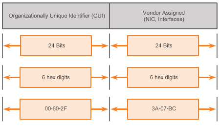
Ethernet MAC address is a 48-bit binary value expressed as 12 hexadecimal digits (4 bits per hexadecimal digit).
MAC addresses must be globally unique. The MAC address value is a direct result of IEEE-enforced rules for vendors to ensure globally unique addresses for each Ethernet device. The IEEE assigns the vendor a 3-byte (24-bit) code, called the Organizationally Unique Identifier (OUI).
- All MAC addresses assigned to a NIC or other Ethernet device must use that vendor’s assigned OUI as the first 3 bytes.
- All MAC addresses with the same OUI must be assigned a unique value (vendor code or serial number) in the last 3 bytes.
The MAC address is often referred to as a Burned-In Address (BIA) because, historically, this address is burned into ROM (Read-Only Memory) on the NIC. This means that the address is encoded into the ROM chip permanently – it cannot be changed by software.
Note: On modern PC operating systems and NICs, it is possible to change the MAC address in software. This is useful when attempting to gain access to a network that filters based on BIA – consequently, filtering, or controlling, traffic based on the MAC address is no longer as secure.
MAC address type:
- Unicast Address:A unicast MAC address is the unique address used when a frame is sent from a single transmitting device to a single destination device.
- Broadcast MAC address: A broadcast packet contains a destination IP address that has all ones (1s) in the host portion. This numbering in the address means that all hosts on that local network (broadcast domain) will receive and process the packet. Many network protocols, such as DHCP and Address Resolution Protocol (ARP), use broadcasts. On Ethernet networks, the broadcast MAC address is 48 ones displayed as hexadecimal FF-FF-FF-FF-FF-FF.
- Multicast MAC address: The multicast MAC address is a special value that begins with 01-00-5E in hexadecimal. The remaining portion of the multicast MAC address is created by converting the lower 23 bits of the IP multicast group address into 6 hexadecimal characters.
ARP
Show ARP table: show ip arp command.
APR issues:
- Broadcasts, create overhead on the media.
- Security: ARP spoofing, or ARP poisoning.
Ethernet Frame
Two styles of Ethernet framing:
- IEEE 802.3 Ethernet standard which has been updated several times to include new technologies
- The DIX Ethernet standard which is now referred to Ethernet II
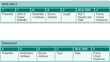
The differences between framing styles are minimal. The most significant difference between the two standards is the addition of a Start Frame Delimiter (SFD) and the change of the Type field to a Length field in the 802.3.
Ethernet II is the Ethernet frame format used in TCP/IP networks.
Frame Size:
Both the Ethernet II and IEEE 802.3 standards define the minimum frame size as 64 bytes and the maximum as 1518 bytes(not including 4 bytes VLAN tag). The Preamble and Start Frame Delimiter fields are not included when describing the size of a frame. So the header length is 14 bytes.
| Layer | Preamble | Start of frame delimiter | MAC destination | MAC source | 802.1Q tag (optional) | Ethertype (Ethernet II) or length | Payload | Frame check sequence (32‑bit CRC) | Interpacket gap |
|---|---|---|---|---|---|---|---|---|---|
| 7 octets | 1 octet | 6 octets | 6 octets | (4 octets) | 2 octets | 46(42)–1500 octets | 4 octets | 12 octets | |
| Layer 2 Ethernet frame | ← 64–1518(1522) octets → | ||||||||
| Layer 1 Ethernet packet | ← 72–1526(1530) octets → | ||||||||
less than 64 bytes in length is considered a “collision fragment” or “runt frame” and is automatically discarded by receiving stations. The IEEE 802.3ac standard, released in 1998, extended the maximum allowable frame size to 1522 bytes. The frame size was increased to accommodate a technology called Virtual Local Area Network (VLAN). 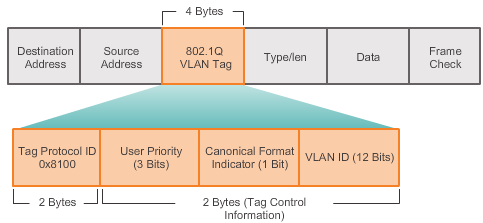 Frame attributes(IEEE 802.3):
- Preamble and Start Frame Delimiter Fields: The Preamble (7 bytes) and Start Frame Delimiter (SFD), also called the Start of Frame (1 byte), fields are used for synchronization between the sending and receiving devices. These first eight bytes of the frame are used to get the attention of the receiving nodes. Essentially, the first few bytes tell the receivers to get ready to receive a new frame.
- Destination MAC Address Field: This 6-byte field is the identifier for the intended recipient. As you will recall, this address is used by Layer 2 to assist devices in determining if a frame is addressed to them. The address in the frame is compared to the MAC address in the device. If there is a match, the device accepts the frame.
- Source MAC Address Field: This 6-byte field identifies the frame’s originating NIC or interface.
- Length Field: For any IEEE 802.3 standard earlier than 1997 the Length field defines the exact length of the frame’s data field. This is used later as part of the FCS to ensure that the message was received properly. Otherwise the purpose of the field is to describe which higher-layer protocol is present. If the two-octet value is equal to or greater than 0x0600 hexadecimal or 1536 decimal, then the contents of the Data field are decoded according to the EtherType protocol indicated. Whereas if the value is equal to or less than 0x05DC hexadecimal or 1500 decimal then the Length field is being used to indicate the use of the IEEE 802.3 frame format. This is how Ethernet II and 802.3 frames are differentiated.
- Data Field: This field (46 – 1500 bytes) contains the encapsulated data from a higher layer, which is a generic Layer 3 PDU, or more commonly, an IPv4 packet. All frames must be at least 64 bytes long. If a small packet is encapsulated, additional bits called a pad are used to increase the size of the frame to this minimum size.
- Frame Check Sequence Field: The Frame Check Sequence (FCS) field (4 bytes) is used to detect errors in a frame. It uses a cyclic redundancy check (CRC). The sending device includes the results of a CRC in the FCS field of the frame. The receiving device receives the frame and generates a CRC to look for errors. If the calculations match, no error occurred. Calculations that do not match are an indication that the data has changed; therefore, the frame is dropped.