Serial communications
A LAN-to-WAN point-to-point connection is also referred to as a serial connection or leased-line connection. This is because the lines are leased from a carrier (usually a telephone company) and are dedicated for use by the company leasing the lines. Companies pay for a continuous connection between two remote sites, and the line is continuously active and available. Leased lines are a frequently used type of WAN access, and they are generally priced based on the bandwidth required and the distance between the two connected points.
Serial and parallel
- Communications across a serial connection is a method of data transmissions in which the bits are transmitted sequentially over a single channel. This is equivalent to a pipe only wide enough to fit one ball at a time. Multiple balls can only go into the pipe, but only one at a time, and they only have one exit point, the other end of the pipe. A serial port is bidirectional, and often referred to as a bidirectional port or a communications port.
- Parallel communications: bits can be transmitted simultaneously over multiple wires. a parallel connection theoretically transfers data eight times faster than a serial connection. Based on this theory, a parallel connection sends a byte (eight bits) in the time that a serial connection sends a single bit.
However, parallel communications do have issues:- crosstalk across wires, especially as the wire length increases.
- Clock skew is also an issue with parallel communications. Clock skew occurs when data across the various wires does not arrive at the same time, creating synchronization issues.
- Finally, most parallel communications supports only one-direction, outbound-only communication from the hard drive.
On most PCs, parallel ports and RS-232 serial ports have been replaced by the higher speed serial Universal Serial Bus (USB) interfaces.
Three important serial communication standards:
- RS-232 – Most serial ports on personal computers conform to the RS-232C or newer RS-422 and RS-423 standards. Both 9-pin and 25-pin connectors are used.
- V.35 – Typically used for modem-to-multiplexer communication, this ITU standard for high-speed, synchronous data exchange combines the bandwidth of several telephone circuits. In the U.S., V.35 is the interface standard used by most routers and DSUs that connect to T1 carriers. V.35 cables are high-speed serial assemblies designed to support higher data rates and connectivity between DTEs and DCEs over digital lines. There is more on DTEs and DCEs later in this section.
- HSSI – A High-Speed Serial Interface (HSSI) supports transmission rates up to 52 Mb/s. Engineers use HSSI to connect routers on LANs with WANs over high-speed lines, such as T3 lines. Engineers also use HSSI to provide high-speed connectivity between LANs, using Token Ring or Ethernet. HSSI is a DTE/DCE interface developed by Cisco Systems and T3 plus Networking to address the need for high-speed communication over WAN links.
Note: Point-to-point connections are not limited to connections that cross land. There are hundreds of thousands of miles of undersea fiber-optic cables that connect countries and continents worldwide.
Time Division Multiplexing
With a leased line, despite the fact that customers are paying for dedicated services, and dedicated bandwidth is provided to the customer, the carrier still uses multiplexing technologies within the network. Multiplexing refers to a scheme that allows multiple logical signals to share a single physical channel. Two common types of multiplexing are time-division multiplexing (TDM) and statistical time-division multiplexing (STDM).
TDM
Bell Laboratories originally invented TDM to maximize the amount of voice traffic carried over a medium. Before multiplexing, each telephone call required its own physical link. This was an expensive and unscalable solution. TDM divides the bandwidth of a single link into separate time slots. TDM transmits two or more channels (data stream) over the same link by allocating a different time slot for the transmission of each channel. In effect, the channels take turns using the link.
TDM is a physical layer concept. It has no regard for the nature of the information that is multiplexed on to the output channel. TDM is independent of the Layer 2 protocol that has been used by the input channels.
TDM can be explained by an analogy to highway traffic. To transport traffic from four roads to another city, all traffic can be sent on one lane if the roads are equally serviced and the traffic is synchronized. If each of the four roads puts a car on to the main highway every four seconds, the highway gets a car at the rate of one each second. As long as the speed of all the cars is synchronized, there is no collision. At the destination, the reverse happens and the cars are taken off the highway and fed to the local roads by the same synchronous mechanism.
This is the principle used in synchronous TDM when sending data over a link. TDM increases the capacity of the transmission link by dividing transmission time into smaller, equal intervals so that the link carries the bits from multiple input sources.
A multiplexer (MUX) at the transmitter accepts three separate signals. The MUX breaks each signal into segments. The MUX puts each segment into a single channel by inserting each segment into a time slot.
A MUX at the receiving end reassembles the TDM stream into the three separate data streams based only on the timing of the arrival of each bit. A technique called bit interleaving keeps track of the number and sequence of the bits from each specific transmission so that they can be quickly and efficiently reassembled into their original form upon receipt. Byte interleaving performs the same functions, but because there are eight bits in each byte, the process needs a bigger or longer time slot.
Examples:
SONET and SDH
On a larger scale, the telecommunications industry uses the Synchronous Optical Networking (SONET) or Synchronous Digital Hierarchy (SDH) standard for optical transport of TDM data. SONET, used in North America, and SDH, used elsewhere, are two closely-related standards that specify interface parameters, rates, framing formats, multiplexing methods, and management for synchronous TDM over fiber.
SONET/SDH takes n bit streams, multiplexes them, and optically modulates the signals. It then sends the signals out using a light emitting device over fiber with a bit rate equal to (incoming bit rate) x n. Thus, traffic arriving at the SONET multiplexer from four places at 2.5 Gb/s goes out as a single stream at 4 x 2.5 Gb/s, or 10 Gb/s. This principle is illustrated in the figure, which shows an increase in the bit rate by a factor of four in time slot T. 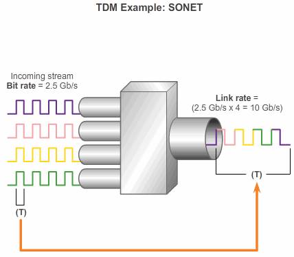
STDM
In the TDM, if one of the companies has cargo to send, the car is loaded. If the company has nothing to send, the car remains empty, but stays on the train. Shipping empty containers is not very efficient. TDM shares this inefficiency when traffic is intermittent, because the time slot is still allocated even when the channel has no data to transmit.
STDM was developed to overcome this inefficiency. STDM uses a variable time slot length allowing channels to compete for any free slot space. It employs a buffer memory that temporarily stores the data during periods of peak traffic. STDM does not waste high-speed line time with inactive channels using this scheme. STDM requires each transmission to carry identification information or a channel identifier.
Demarcation Point
The local loop refers to the line from the premises of a telephone subscriber to the telephone company central office.
Deregulation forced telephone companies to unbundle their local loop infrastructure to allow other suppliers to provide equipment and services. This led to a need to delineate which part of the network the telephone company owned and which part the customer owned. This point of delineation is the demarcation point.
The demarcation point marks the point where your network interfaces with a network that is owned by another organization. In telephone terminology, this is the interface between customer premises equipment (CPE) and network service provider equipment. The demarcation point is the point in the network where the responsibility of the service provider end.
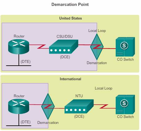
The differences in demarcation points can best be shown using ISDN. In the United States, a service provider provides the local loop into the customer premises, and the customer provides the active equipment such as the CSU/DSU on which the local loop is terminated.
A router serial port is required for each leased-line connection. If the underlying network is based on the T-carrier or E-carrier technologies, the leased line connects to the network of the carrier through a CSU/DSU. The purpose of the CSU/DSU is to provide a clocking signal to the customer equipment interface from the DSU and terminate the channelized transport media of the carrier on the CSU. The CSU also provides diagnostic functions such as a loopback test. 
DCE DTE
From the point of view of connecting to the WAN, a serial connection has a DTE device at one end of the connection and a DCE device at the other end. The connection between the two DCE devices is the WAN service provider transmission network, as shown in the figure. In this example:
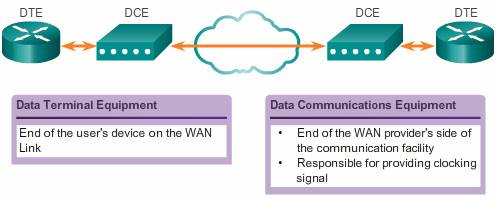
- The CPE, which is generally a router, is the DTE. The DTE could also be a terminal, computer, printer, or fax machine if they connect directly to the service provider network.
- The DCE, commonly a modem or CSU/DSU, is the device used to convert the user data from the DTE into a form acceptable to the WAN service provider transmission link. This signal is received at the remote DCE, which decodes the signal back into a sequence of bits. The remote DCE then signals this sequence to the remote DTE.
The Electronics Industry Association (EIA) and the International Telecommunication Union Telecommunications Standardization Sector (ITU-T) have been most active in the development of standards that allow DTEs to communicate with DCEs.
Serial Cables
The DTE/DCE interface for a particular standard defines the following specifications:
- Mechanical/physical – Number of pins and connector type
- Electrical – Defines voltage levels for 0 and 1
- Functional – Specifies the functions that are performed by assigning meanings to each of the signaling lines in the interface
- Procedural – Specifies the sequence of events for transmitting data
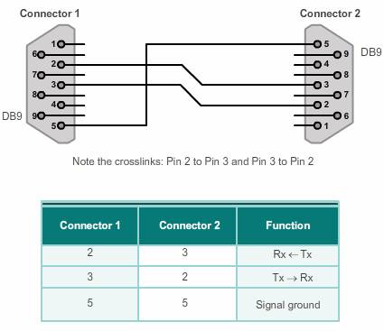
The original RS-232 standard only defined the connection of DTEs with DCEs, which were modems. However, to connect two DTEs, such as two computers or two routers in a lab, a special cable called a null modem eliminates the need for a DCE. In other words, the two devices can be connected without a modem. A null modem is a communication method to directly connect two DTEs using a RS-232 serial cable. With a null modem connection, the transmit (Tx) and receive (Rx) lines are cross-linked.
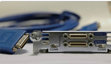
 The cable for the DTE to DCE connection is a shielded serial transition cable. The router end of the shielded serial transition cable may be a DB-60 connector, which connects to the DB-60 port on a serial WAN interface card.
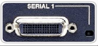 To support higher port densities in a smaller form factor, Cisco has introduced a Smart Serial cable. The router interface end of the Smart Serial cable is a 26-pin connector that is significantly more compact than the DB-60 connector.
Serial Bandwidth
Bandwidth refers to the rate at which data is transferred over the communication link. The underlying carrier technology depends on the bandwidth available. There is a difference in bandwidth points between the North American (T-carrier) specification and the European (E-carrier) system. Optical networks also use a different bandwidth hierarchy, which again differs between North America and Europe. In the U.S., Optical Carrier (OC) defines the bandwidth points.
In North America, the bandwidth is usually expressed as a digital signal level number (DS0, DS1, etc.), which refers to the rate and format of the signal. The most fundamental line speed is 64 kb/s, or DS-0, which is the bandwidth required for an uncompressed, digitized phone call. Serial connection bandwidths can be incrementally increased to accommodate the need for faster transmission. For example, 24 DS0s can be bundled to get a DS1 line (also called a T1 line) with a speed of 1.544 Mb/s. Also, 28 DS1s can be bundled to get a DS3 line (also called a T3 line) with a speed of 44.736 Mb/s. Leased lines are available in different capacities and are generally priced based on the bandwidth required and the distance between the two connected points.
OC transmission rates are a set of standardized specifications for the transmission of digital signals carried on SONET fiber-optic networks. The designation uses OC, followed by an integer value representing the base transmission rate of 51.84 Mb/s. For example, OC-1 has a transmission capacity of 51.84 Mb/s, whereas an OC-3 transmission medium would be three times 51.84 Mb/s, or 155.52 Mb/s.
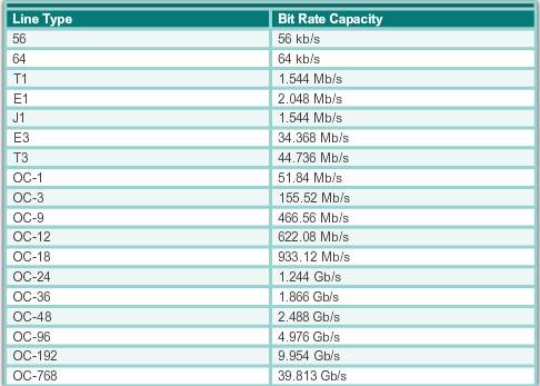
Note: E1 (2.048 Mb/s) and E3 (34.368 Mb/s) are European standards like T1 and T3, but with different bandwidths and frame structures.
WAN encapsulation
The following are short descriptions of each type of WAN protocol:
- HDLC –High-Level Data Link Control (HDLC) is a bit-oriented code-transparent synchronous data link layer protocol developed by the International Organization for Standardization (ISO). The default encapsulation type on point-to-point connections, dedicated links, and circuit-switched connections when the link uses two Cisco devices. HDLC is now the basis for synchronous PPP used by many servers to connect to a WAN, most commonly the Internet.
- PPP – Provides router-to-router and host-to-network connections over synchronous and asynchronous circuits. PPP works with several network layer protocols, such as IPv4 and IPv6. PPP uses the HDLC encapsulation protocol, but also has built-in security mechanisms such as PAP and CHAP.
- Serial Line Internet Protocol (SLIP) – A standard protocol for point-to-point serial connections using TCP/IP. SLIP has been largely displaced by PPP.
- X.25/Link Access Procedure, Balanced (LAPB) – An ITU-T standard that defines how connections between a DTE and DCE are maintained for remote terminal access and computer communications in public data networks. X.25 specifies LAPB, a data link layer protocol. X.25 is a predecessor to Frame Relay.
- Frame Relay – An industry standard, switched, data link layer protocol that handles multiple virtual circuits. Frame Relay is a next generation protocol after X.25. Frame Relay eliminates some of the time-consuming processes (such as error correction and flow control) employed in X.25.
- ATM – The international standard for cell relay in which devices send multiple service types, such as voice, video, or data, in fixed-length (53-byte) cells. Fixed-length cells allow processing to occur in hardware; thereby, reducing transit delays. ATM takes advantage of high-speed transmission media such as E3, SONET, and T3.