VPN
Organizations use VPNs to create an end-to-end private network connection over third-party networks such as the Internet or extranets. The tunnel eliminates the distance barrier and enables remote users to access central site network resources.
A VPN is a private network created via tunneling over a public network, usually the Internet. A VPN is a communications environment in which access is strictly controlled to permit peer connections within a defined community of interest.
The first VPNs were strictly IP tunnels that did not include authentication or encryption of the data. For example, Generic Routing Encapsulation (GRE) is a tunneling protocol developed by Cisco that can encapsulate a wide variety of network layer protocol packet types inside IP tunnels. This creates a virtual point-to-point link to Cisco routers at remote points over an IP internetwork.
Today, a secure implementation of VPN with encryption, such as IPsec VPNs, is what is usually meant by virtual private networking.
To implement VPNs, a VPN gateway is necessary. The VPN gateway could be a router, a firewall, or a Cisco Adaptive Security Appliance (ASA). An ASA is a standalone firewall device that combines firewall, VPN concentrator, and intrusion prevention functionality into one software image.
The benefits of a VPN include the following:
- Cost savings – VPNs enable organizations to use cost-effective, third-party Internet transport to connect remote offices and remote users to the main site; therefore, eliminating expensive, dedicated WAN links and modem banks. Furthermore, with the advent of cost-effective, high-bandwidth technologies, such as DSL, organizations can use VPNs to reduce their connectivity costs while simultaneously increasing remote connection bandwidth.
- Scalability – use the Internet infrastructure within ISPs and devices, able to add large amounts of capacity without adding significant infrastructure.
- Compatibility with broadband technology – VPNs allow mobile workers and telecommuters to take advantage of high-speed, broadband connectivity, to access to their organizations’ networks. Broadband connectivity provides flexibility and efficiency. High-speed, broadband connections also provide a cost-effective solution for connecting remote offices.
- Security – VPNs can include security mechanisms that provide the highest level of security by using advanced encryption and authentication protocols.
There are two types of VPN networks:
- Site-to-site
- Remote access
Site-to-Site VPN
A site-to-site VPN is created when devices on both sides of the VPN connection are aware of the VPN configuration in advance.
The VPN remains static, and internal hosts have no knowledge that a VPN exists. In a site-to-site VPN, end hosts send and receive normal TCP/IP traffic through a VPN “gateway”. The VPN gateway is responsible for encapsulating and encrypting outbound traffic for all traffic from a particular site. The VPN gateway then sends it through a VPN tunnel over the Internet to a peer VPN gateway at the target site. Upon receipt, the peer VPN gateway strips the headers, decrypts the content, and relays the packet toward the target host inside its private network.
A site-to-site VPN is an extension of a classic WAN network. Site-to-site VPNs connect entire networks to each other, for example, a branch office network to a company headquarters network.
In the past, a leased line or Frame Relay connection was required to connect sites, but because most corporations now have Internet access, these connections can be replaced with site-to-site VPNs.
Remote-access VPNs
Where a site-to-site VPN is used to connect entire networks, a remote-access VPN supports the needs of telecommuters, mobile users, and extranet, consumer-to-business traffic. A remote-access VPN is created when VPN information is not statically set up, but instead allows for dynamically changing information, and can be enabled and disabled.
Remote-access VPNs support a client/server architecture, where the VPN client (remote host) gains secure access to the enterprise network via a VPN server device at the network edge.
VPN client software may need to be installed on the mobile user’s end device. (Cisco AnyConnect VPN Client software ) The encrypted data is then sent over the Internet to the VPN gateway at the edge of the target network. Upon receipt, the VPN gateway behaves as it does for site-to-site VPNs.
Note: The Cisco AnyConnect Secure Mobility Client software builds on prior Cisco AnyConnect VPN Client and Cisco VPN Client offerings to improve the always-on VPN experience across more laptop and smart phone-based mobile devices. This client supports IPv6.
GRE
Generic Routing Encapsulation (GRE) is one example of a basic, non-secure, site-to-site VPN tunneling protocol. GRE is a tunneling protocol developed by Cisco that can encapsulate a wide variety of protocol packet types inside IP tunnels. GRE creates a virtual point-to-point link to Cisco routers at remote points, over an IP internetwork.
It can encapsulate multiple protocol packet types inside an IP tunnel.
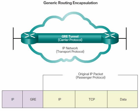
A tunnel interface supports a header for each of the following:
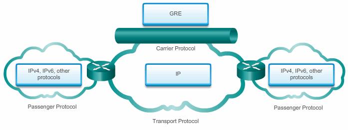
- An encapsulated protocol (or passenger protocol), such as IPv4, IPv6, AppleTalk, DECnet, or IPX
- An encapsulation protocol (or carrier), such as GRE
- A transport delivery protocol, such as IP, which is the protocol that carries the encapsulated protocol
IP tunneling using GRE enables network expansion across a single-protocol backbone environment. It does this by connecting multiprotocol subnetworks in a single-protocol backbone environment.
Characteristics:

- GRE is defined as an IETF standard (RFC 2784).
- In the outer IP header, 47 is used in the protocol field to indicate that a GRE header will follow.
- GRE encapsulation uses a protocol type field in the GRE header to support the encapsulation of any OSI Layer 3 protocol. Protocol Types are defined in RFC 1700 as “EtherTypes”.
- GRE itself is stateless; by default it does not include any flow-control mechanisms.
- GRE does not include any strong security mechanisms to protect its payload.
- The GRE header, together with the tunneling IP header indicated in the figure, creates at least 24 bytes of additional overhead for tunneled packets.
GRE configuration
To implement a GRE tunnel, the network administrator must first learn the IP addresses of the endpoints.

After that, there are five steps to configuring a GRE tunnel:
Step 1. Create a tunnel interface using the interface tunnel number command.
Step 2. Specify the tunnel source IP address ( or local physical interface name).
Step 3. Specify the tunnel destination IP address.
Step 4. Configure an IP address for the tunnel interface.
Step 5. (Optional) Specify GRE tunnel mode as the tunnel interface mode by command tunnel mode gre ip . GRE tunnel mode is the default tunnel interface mode for Cisco IOS software.
Example
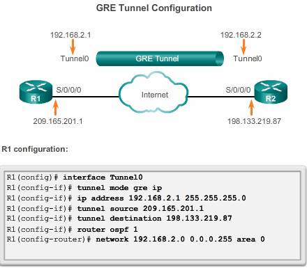
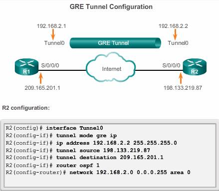
The minimum configuration requires specification of the tunnel source and destination addresses. The IP subnet must also be configured to provide IP connectivity across the tunnel link.
Both tunnel interfaces have the tunnel source set as the local serial S0/0/0 interface and the tunnel destination set as the peer router serial S0/0/0 interface. The IP address is assigned to the tunnel interfaces on both routers.
OSPF has also been configured to exchange routes over the GRE tunnel. Note, don’t advertising the physical interface which is used to establish the tunnel, or else, the GRE recursive routing will occor and interface flapping
https://supportforums.cisco.com/document/96211/gre-recursive-loops
Note: When configuring GRE tunnels, it can be difficult to remember which IP networks are associated with the physical interfaces and which IP networks are associated with the tunnel interfaces. Remember that before a GRE tunnel is created, the physical interfaces have already been configured. The tunnel source and tunnel destination commands reference the IP addresses of the preconfigured physical interfaces. The ip address command on the tunnel interfaces refers to an IP network specifically manufactured for the purposes of the GRE tunnel.
Verify GRE
There are several commands that can be used to monitor and troubleshoot GRE tunnels.
- To determine whether the tunnel interface is up or down, use the show ip interface brief command.
- To verify the state of a GRE tunnel, use the
show interface tunnelcommand. The line protocol on a GRE tunnel interface is up as long as there is a route to the tunnel destination. Before implementing a GRE tunnel, IP connectivity must already be in effect between the IP addresses of the physical interfaces on opposite ends of the potential GRE tunnel. - If OSPF has also been configured to exchange routes over the GRE tunnel, verify that an OSPF adjacency has been established over the tunnel interface using the show ip ospf neighbor command.