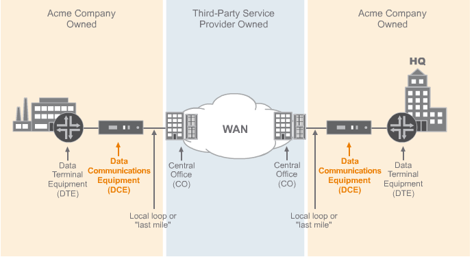
CPE( customer premises equipment): any communication equipment located on the customer’s premises that is used to connect to the service provider’s network. The customer can own the CPE or lease it from the service provider.
CO ( Central office): service provider’s nearest exchange.
Local Loop or “last mile” refers to the copper or fiber cable that conncects the CPE to the CO.
DTE (data terminal equipment): is the device generating the data.
DCE(data communication equipment): is the device that actually puts the data on the local loop.

Plain Old Telephone Service(POTS) line
Plain Old Telephone Service (POTS) lines are analog copper phone lines capable of data transfer speeds of up to 30 kbps.
T1 Line
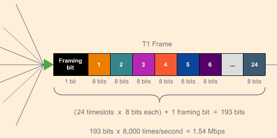
A T1 line is a dedicated copper telephone line that supports data rates of 1.54 Mbps. A T1 line operates at Layer 1 or the Physical layer and is commonly available in North American and Japan. A T1 line consists of 24 individual channels or DS0s, each of which supports 64 Kbps. Each channel or DS0 can transport voice or data. A customer can lease an entire T1 line or only a few channels, which is known as fractional T1 service. The equivalent line outside of North America and Japan is an E1 line.
TDM( time division multiplexing)
Time Division Multiplexing (TDM) is the combining or “multiplexing” of voice and data signals from different devices into a single link.
T1 frame: 1bit of Framing bit; 24 timeslots is carrying 24 specific types of traffic, each time slot is 8 bits.

DS0 is the basic digital signaling rate. DS stands for Digital Signal, and is a system of classifying digital circuits according to the rate and format of the signal. A DS0 offers 64 Kbps of bandwidth—the amount of bandwidth usually used for one telephone voice channel.
DS1 signal is the signal or logical bit pattern carried on a T1 line and is the equivalent of 24 DS0s or channels.
Difference between T1 and DS1
- DS1 refers to the digital signal service provided over the wire. A DS1 signal offers 1.54 Mbps of bandwidth and has a specific format. It might be transported over a T1 line or another type of line.
- T1 refers to the physical line, a copper wire, carrying a DS1 signal.
- If a DS1 circuit is transported over another type of material, such as fiber, it is no longer a T1.
T3 line
A T3 line is a dedicated copper telephone line that supports data rates of 44.74 Mbps and like a T1, is also built on the base DS0 signal. A T3 is 28 DS1s—or 672 DS0s—bundled together.
E1 line (European Standard)
E1 is a dedicated copper telephone line that supports data rates of 2.05 Mbps. An E1 line operates at Layer 1 or the Physical layer and is commonly available world-wide with the exception of North America and Japan where T1 lines are used. An E1 line consists of 32 individual channels or DS0s, each of which supports 64 Kbps. Each channel or DS0 can transport voice or data. A customer can lease an entire E1 line or only a few channels, which is known as fractional E1 service.
E3 is a dedicated copper telephone line that supports data rates of 34.37 Mbps and like an E1, is also built on the base DS0 signal. An E3 is 16 E1s—or 512 DS0s—bundled together.
Fiber optic
SONET(North American and Japan):
Synchronous Optical Network (SONET) is a standard that defines a basic frame format and a hierarchy of signaling speeds for use on a fiber optic line. SONET operates at Layer 1 or the Physical Layer and is available in North America and Japan.
SDH(European standard):
Synchronous Digital Hierarchy (SDH) is a standard that defines a basic frame format and a hierarchy of signaling speeds for use on a fiber optic line. SDH operates at Layer 1 or the Physical Layer and is available outside of North America and Japan.
SONET and SDH both use time-divistion multiplexing.
OTN:
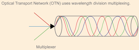
Optical Transport Network (OTN) uses Wavelength Division Multiplexing(WDM) to transport data over optical networks. OTN systems in use today can operate on 40 or even 80 channels simultaneously. Incoming signals can be SONET, SDH, Ethernet, or native OTN traffic.
WDM:
Wavelength division multiplexing transmits incoming signals simultaneously over a fiber optic line by putting each signal into a different wavelength (or color) of light. On the receiving end, the de-multiplexer recognizes each different wavelength of light and turns it back into the signal it received.
