In this lab, I am going to build a small network environment, which include a simple webserver(pc1), Router1 , router2, and client(PC2).
Step1, draw a topology and assign network address .The topology and addresses are show in the picture bellow.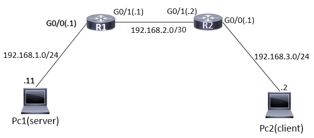
Step2,configure the server.
Use the virtual machine(virtual box) in my laptop as a webserver, choose the “bridged to host network adaptor” as show in the picture.
Then turn on the virtual machine, open server manager, add new role, choose Web service(IIS).choose default settings, Click next until finish.
After the installation, browse to “C:\inetpub\wwwroot” , create a new html file called index.html.Use notepad to edit it. I added <div>
<p style=”text-align:center; font-size:20px; color:#333;padding:20px 10px”> Hello every one, this is the test page of the frankfu.com</p>
</div> between the <body></body> tag.
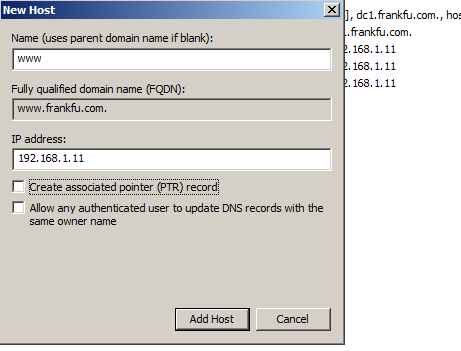
Make sure NDS server also installed, and create a zone called the name you like, I pick frankfu.com. right click the blank area on the right hand side panel, choose”New Host(A or AAAA)” ,type”www” in the “Name” area, “192.168.1.11” in the “IP address” area, then click “add host”.

Step 3,Assign the IP address to the router interface and PCs.
On Pc2, assign ip address:192.168.3.2; subnet mask: 255.255.255.0; default gateway:192.168.3.1; NDS server: 192.168.1.11.
In router 1
r1#conf t
r1(config)#int g0/0
r1(config-if)#ip add 192.168.1.1 255.255.255.0
r1(config-if)#no shutdown
r1(config-if)#
%LINK-5-CHANGED: Interface GigabitEthernet0/0, changed state to up
r1(config-if)#int g0/1
r1(config-if)#ip add 192.168.2.1 255.255.255.252
r1(config-if)#no shutdown
%LINK-5-CHANGED: Interface GigabitEthernet0/1, changed state to up
r1(config)#ip route 192.168.3.0 255.255.255.0 192.168.2.2
r1(config)#do show ip route
%LINEPROTO-5-UPDOWN: Line protocol on Interface GigabitEthernet0/1, changed state to up
Codes: L – local, C – connected, S – static, R – RIP, M – mobile, B – BGP
D – EIGRP, EX – EIGRP external, O – OSPF, IA – OSPF inter area
N1 – OSPF NSSA external type 1, N2 – OSPF NSSA external type 2
E1 – OSPF external type 1, E2 – OSPF external type 2, E – EGP
i – IS-IS, L1 – IS-IS level-1, L2 – IS-IS level-2, ia – IS-IS inter area
* – candidate default, U – per-user static route, o – ODR
P – periodic downloaded static route
Gateway of last resort is not set
192.168.2.0/24 is variably subnetted, 2 subnets, 2 masks
C 192.168.2.0/30 is directly connected, GigabitEthernet0/1
L 192.168.2.1/32 is directly connected, GigabitEthernet0/1
S 192.168.3.0/24 [1/0] via 192.168.2.2
r1(config)#ip name-server 192.168.1.11
In router 2
r2(config-if)#ip add 192.168.2.2 255.255.255.252
r2(config-if)#no shutdown
r2(config-if)#
%LINK-5-CHANGED: Interface GigabitEthernet0/1, changed state to up
r2(config-if)#
%LINEPROTO-5-UPDOWN: Line protocol on Interface GigabitEthernet0/1, changed state to up
r2(config-if)#int g0/0
r2(config-if)#ip add 192.168.3.2 255.255.255.0
r2(config-if)#no shut
r2(config-if)#exit
r2(config)#ip route 192.168.1.0 255.255.255.0 192.168.2.1
r2(config)#do show ip route
Codes: L – local, C – connected, S – static, R – RIP, M – mobile, B – BGP
D – EIGRP, EX – EIGRP external, O – OSPF, IA – OSPF inter area
N1 – OSPF NSSA external type 1, N2 – OSPF NSSA external type 2
E1 – OSPF external type 1, E2 – OSPF external type 2, E – EGP
i – IS-IS, L1 – IS-IS level-1, L2 – IS-IS level-2, ia – IS-IS inter area
* – candidate default, U – per-user static route, o – ODR
P – periodic downloaded static route
Gateway of last resort is not set
S 192.168.1.0/24 [1/0] via 192.168.2.1
192.168.2.0/24 is variably subnetted, 2 subnets, 2 masks
C 192.168.2.0/30 is directly connected, GigabitEthernet0/1
L 192.168.2.2/32 is directly connected, GigabitEthernet0/1
r2(config)#ip name
r2(config)#ip name-server 192.168.1.11
Test the link and web server functionality.
Try to ping r1 G0/0, G0/1;r2 G0/1, G0/0 pc2 from Pc1. then ping r2 G0/0, G0/1, r1 G0/1, G0/0; pc1 from pc2. if can not ping the pc2 or server in pc1, try to turn off the firewall and retry.
Open a browser in Pc2, and type your domain name(frankfu.com in my lab) to test the functionality of Web Server. Then try www.frankfu.com. If everything works, go to next step.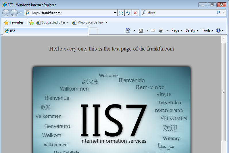
If not function, do the following trouble shooting:
- check the proxy server setting of PC1.
- use show command to check the configuration of R1 and R2.
Step 4, Edit and Apply the ACL
- Edit the ACL.
- We will create a ACL to deny the http service for Pc2, which is using TCP protocol and port:80 to transfer data. We don’t want the ACL to affect other clients, so create it on the router most closed to the Pc2, which is R2.
- On router 2.
- r2(config)#access-list 101 deny tcp 192.168.3.0 0.0.0.255 any eq 80r2(config)#do show ip access-listr2(config)#access-list 101 permit icmp 192.168.3.0 0.0.0.255 anyr2(config)#do show ip access-listExtended IP access list 10110 deny tcp 192.168.3.0 0.0.0.255 any eq www
20 permit icmp 192.168.3.0 0.0.0.255 any
r2(config)#
- Apply the ACL.
- r2(config)#int g0/0r2(config-if)#ip access-group 101 in
- Test connectivity: Open a browser in pc2 and try to open site frankfu.com again, it should not be open, because http traffic been blocked. Open a CMD terminal, you can ping the server 192.168.1.11, because ICMP is permited.