The Devices:
- Controller DWC-1000 X1
- DWL-3600AP X3
- Router (cisco C1941)
Notice:
Wireless LAN controller is a layer 2 device, can run multiple VLANs, so if you want to setup multiple SSID for different network, you need to setup VLANs. After all, you need a layer 3 device ( router, or purchase a license to enable the Option port, or else, the NAT will not work on option port) to route traffic between different VLANs and WAN traffic. In this project, I used router on stick to provide internet access. The topology is as bellow:
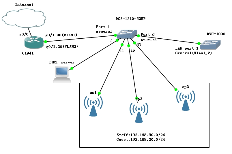
There will be two ssid (network):
- staff (VLAN1: 192.168.90.0/24) for staff use, can access printer, file server, extra, client get IP configuration from company DHCP server.
- guest (VLAN2: 192.168.20.0/24) for guest use, only have access to internet, client get IP configuration from WLAN controller.
Physical connection:
- Port 1 in DGS switch will connect to the router port. This port permits VLAN 1 and 2 traffic
- Port 2 in DGS connect to DHCP server for scope 192.168.90.0/24. Access port in VLAN1
- Port 6 in DGS will connect to the Wireless controller LAN port 1. This port permits VLAN 1 and 2 traffic.
- Port 41-43 in DGS will connect to the wireless access points.This port permits VLAN 1 and 2 traffic.
Steps to setup
First plan your VLAN and IP address for the controller and access points.
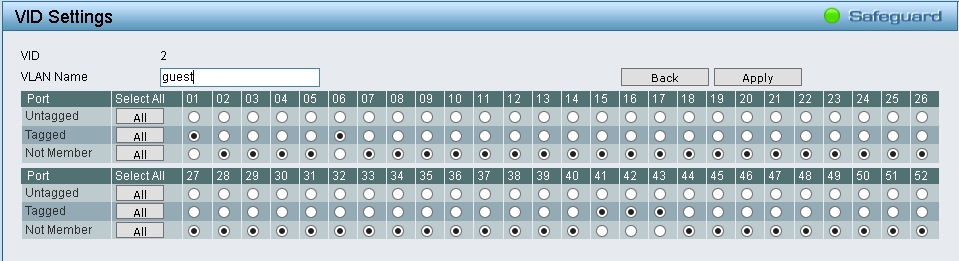
- In DGS switch, Go to VLAN > 802.1Q VLAN, CLick 1 under VID column, make sure all ports are untagged, click back;
- Add VID 2, name ” Guest”, then click 2 under VID column, choose untagged under port 01, 06, 41,42,43, all others not member.
- The IP address 192.168.90.100/24 for controller and 192.168.90.11-13 for five APs, default gateway 192.168.90.1.
Note: Before connecting all the device altogether, you need to know the default IP address of the Controller is 192.168.10.1/24, but the IP address of the access point is 10.90.90.91/8. So if connect them together, the controller will not discover the access point.

There are two ways to solve this

First method:  The access point use DHCP to get IP address by default, basically you connect all APs and WLAN controller to a switch, then you can configure the DHCP server on the controller or dedicated DHCP server, and assign the IP addresses within 192.168.10.1/24 to the APs,
then connect them together, the draw back of this method is you don't know which address with which access point, hence lead to hard management.

Manually assign IP address to the Access point:

1. Connect first AP(better to label it with a sticker or marker) to your PC via Ethernet cable and power supply. First configure you PC's IP address to 192.168.10.100/24, enter 192.168.10.1 in browser,default username/password(admin/admin),change the password for a securer one,
configure IP address in the Setup > Network Settings > LAN setup configuration, enter 192.168.90.100 in the IP address, then 255.255.255.0 in the Subnet mask.
You will lose connection if you save the settings. Then change your PC's IP addrss to 192.168.90.12/24, type 192.168.90.100 in browser, then user name and password.

2. Set up your PC's IP address to any one in same network as 10.90.90.91/8 such as 10.90.90.11/8. then type 10.90.90.91 in your web browser. You browser will warn that the link is not safe, click advanced, then proceed any way.

3. In the Basic setting or Ethernet setting, setup the IP Address configuration method to manual, then type 192.168.90.11, subnet mask 255.255.255.0, default gateway 192.168.90.1, DNS: according to your Network setup. Repeate this step for rest of the APs and assign 192.168.90.12, 192.168.90.13.
Note, you need to configure a DHCP exclusion range, which includes the 192.168.90.11-13 to avoid IP address conflict.
Setup VLANs on the WLAN controller:
Go to the SETUP > VLAN settings > VLAN Configuration, click Add, Name: guest, ID:2, tick Inter VLAN routing Enable, captive Portal type: free.
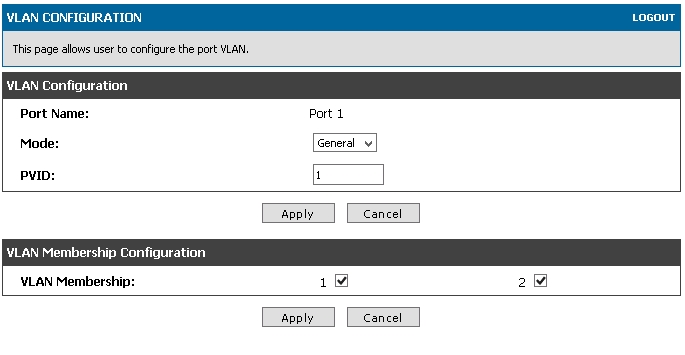
Then go to SETUP > VLAN settings > PORT VLANS, tick Port 1, click Edit, Mode: General, PVID 1, click first Apply down the VLAN configuration, above VLAN Membership configuratoin, then tick 1 and 2 in VLAN membership. click second Apply .
Configure VLAN info for APs:
Then go to SETUP > VLAN settings >Multi VLAN subnets, tick VLAN 1, click Edit, type 192.168.90.100 after IP address, 255.255.255.0 after subnet mask, DHCP mode: none, cause we will use windows server DHCP service to assign IP info to all client connect to SSID staff.click save settings.
Then go to SETUP > VLAN settings >Multi VLAN subnets again, tick VLAN2, click Edit, type IP address 192.168.20.2 , 255.255.255.0, DHCP mode: DHCP server. Domain Name: Guest, starting IP address, 192.168.20.10, ending IP address 192.168.20.254, default gateway: 192.168.20.1, Primary DNS server according to your network setting, Lease Time: for guest, I prefer a shorter one, such as 3 or 4 hours.
Click saving settings.
Configure Profiles:
Then go to ADVANCED, AP Profile, tick the 1-default, click configure SSID, click Edit in first line.
- SSID: staff
- VLAN:1
- Security: WPA/WPA2, WPA personal
- WPA version: WPA2
- WPA ciphers: TKIP, CCMP
- WPA Key: enter the password you want to configure
Leave all others default, click Save settings.
Then go to ADVANCED, AP Profile, tick the 1-default, click configure SSID, tick the second line, click Edit.
- SSID: guest
- VLAN: 2
- Security: WPA/WPA2, WPA personal
- WPA version: WPA2
- WPA ciphers: TKIP, CCMP
- WPA Key: enter the password you want to configure
Associate profile to access points
Go to status > access point info > Authentication Failure status. The access points will be discoverd if they are in same network with the WLAN controller. Troubleshooting if they are not here.
Select an AP and click Manage, then the status will change from No Database entry, to authenticated, then to managed.
Repeat for all other APs. The successfully manged APs will show in status > access point info >Manged AP status.
Configuration on router
On the Cisco C1941 router, configure the NAT and default routing:
interface GigabitEthernet0/0

 description PrimaryWAN

 ip address WAN_IP_address subnet_mask

 ip nat outside

interface GigabitEthernet0/1

 description LAN

 no ip address

interface GigabitEthernet0/1.90

 description STAFF-LAN

 encapsulation dot1Q 1 native

 ip address 192.168.90.1 255.255.255.0

 ip nat inside

interface GigabitEthernet0/1.20

 description GUEST-LAN

 encapsulation dot1Q 2

 ip address 192.168.20.1 255.255.255.0

 ip nat inside


ip nat inside source list 190 interface GigabitEthernet0/0 overload

Access-list 190 Remark ==NAT service==

Access-list 190 permit ip 192.168.90.0 0.0.0.255 any

Access-list 190 permit ip 192.168.20.0 0.0.0.255 any

Ip nat inside source list 190 interface g0/0 overload
To restrict access from guest LAN to Staff LAN, we can create a access-control list:
access-list 120 deny ip 192.168.20.0 0.0.0.255 192.168.90.0 0.0.0.255

interface g0/1.20

ip access-group 120 in
Alternative
Cisco WLAN, AD RADIUS, and Group Policy