Networking preparation
The topology for this project is this:
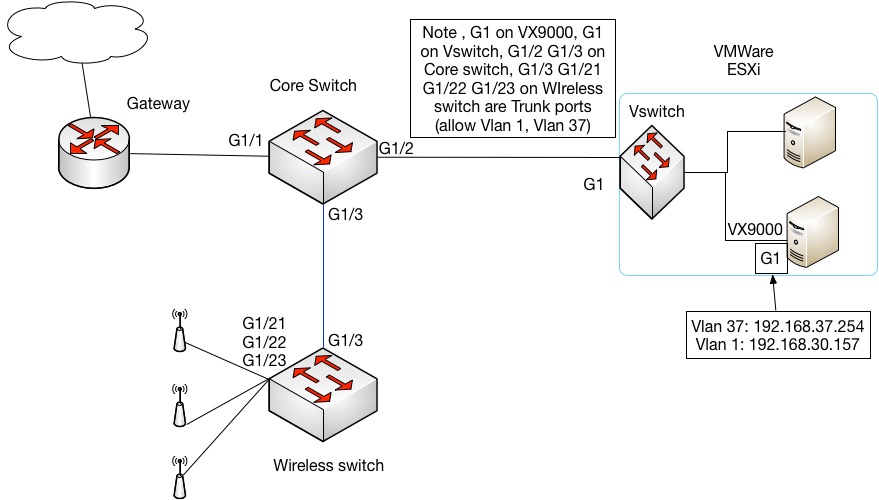
We chose VX9000 as the wireless controller and mode 71xx Access points. The network is shown as above, the corporate current data network 192.168.30.0/23 and running on VLAN 1 on the switch, and the Guest wireless network will be on VLAN 37. We will host the Wireless controller VX9000 virtual instance on a VMware ESXi, which was licensed for one LAN port (Ge1), 60 APs, and also Routing, NAT functionalities.
IP addresses for guest wireless network:
- Management IP address of the Vlan1 on VX9000: 192.168.30.157 /23
- Wireless network IP: 192.168.37.0 / 24
- Default gateway: 192.168.37.254
- DNS server: 8.8.8.8
- DHCP server: VX9000
- RADIUS server: VX9000
- NAT: Interface Vlan 1 (outside) Vlan 37 (inside) on VX9000
Access Point: Interface get IP from DHCP server.
First of all, we need to enable VLAN 37 on the whole network. Make sure the ports are trunks and VLAN 37 is allowed, which connecting between switches, between the VMware ESXi and switch, between switch and wireless AP. This configuration on the switches are easy, the way to setup the VLAN on the VMware ESXI will be talked about soon.
Enable Vlan on VMWare ESXi
VLANs are a great tool to manage business networks and VMware knows that very well. We’ll show you how you can configure ESX(i) to tag packets and how to create virtual switches for your VLANs.
First, enable VLAN architecture on ESXi:
First of all, click F2 and access the ESX(i) console to enable VLAN architecture awareness. Select Configure Management Netowrk.
Enable VLAN tagging specifying 4095 as value:
Specify an IP address for the management network adapter:
Define DNS servers:
Press Esc and confirm:
Now your ESX(i) is VLAN architecture aware.
Second, create virtual switches
Note this can be done on vSphere, not WEB Interface.
- Click Home > Inventory > click the host machine node.
- In the right pane, click configuration, In the Hardware category, click Networking.
- In the right hand side, click properties... .
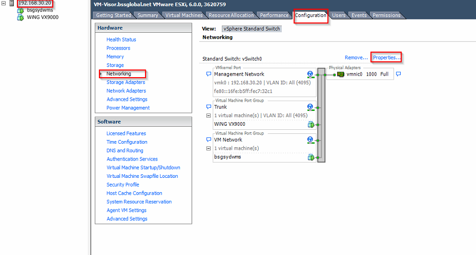
Because the default Virtual machine port group does not allow other VLANs except the native VLAN, Now we are going to add another Virtual machine Port group, which allows VLAN taggingIn the Ports.
- click Add… button, choose virtual machine
- In the Network Label, give it a descriptive name, in this example, I choose Trunk, click the drop down menu in the VLAN ID, choose ALL (4095), click next, then finish.
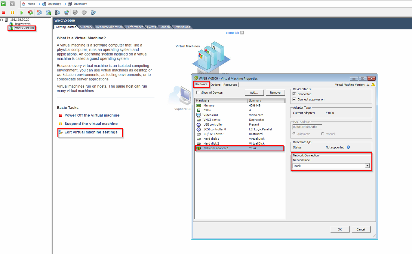
Then we connect our wireless controller VM to the Virtual machine port group.
Expand the host machine node, then click the wireless controller vm node, click Edit virtual machine settings, in hardware tab, click Network adapter 1, in the right hand side, under network connection, choose the Trunk in the drop down menu.
Reference: http://thesolving.com/virtualization/how-to-manage-vlans-and-virtual-switches-on-esxi-vsphere/
Configure the switch port on wireless controller and wireless access points
First We will enable trunk mode and allowed VLANs on the wireless controller port:
In the controller GUI configuration page, go to the Configuration > Devices > VX9000 >Profile Overrides > Interface > Ethernet Ports > ge1
In Basic configuration tab, Under switching mode, Choose the Trunk for mode, native vlan : 1, tag Native VLAN: uncheck ( if your native vlan is 1), Allow VLANs : 1, 37.
(Optional) In Security tab, under Trust, tick Trust DHCP response if you want to configure the VX9000 as DHCP server.
Then We will enable trunk mode and allowed VLANs on the wireless access points port:
In the controller GUI configuration page, go to the Configuration > Profiles > default-ap71xx > Interface > Ethernet Ports > ge1
In Basic configuration tab, Under switching mode, Choose the Trunk for mode, native vlan : 1, tag Native VLAN: uncheck ( if your native vlan is 1), Allow VLANs : 1, 37.
DHCP server on the Controller ( optional)
In my example, I am going to use the VX9000 as the DHCP server for APs and Guest clients, so I will configure this in this step.
- Create DHCP server Policy and Pool.
Go to Configuration > Services > DHCP server Policy
Click Add in the right pane, Give it a name : Guest DHCP, click Continue. In the DHCP Pool pane, click Add button, then type the Pool name Guest default.
In Basic Setting tab: Network: 192.168.37.0/24; DNS servers: IP, 8.8.8.8 click down arrow; Default Routers : IP, 192.168.37.254; IP Address Ranges: configure this if you want to limit the range of IP addresses assigned to end user; click OK, exit.
2. Assign the Policy to the Wireless controller
We only need the VX9000 to be the DHCP server, so we go to Configuration > Devices > VX9000 >Profile Overrides >Services
Under DHCP server: choose the DHCP server Policy Guest DHCP.
Also make sure in the Configuration > Devices > VX9000 >Profile Overrides > Interface > Ethernet Ports > ge1. In Security tab, under Trust, tick Trust DHCP response.
3. Enable the DHCP on client interfaces
Now we can let virtual interface get IP address from DHCP server:
Configuration > Profiles > default-ap71xx > Interface > Virtual Interfaces
Click Add button, VLAN ID: 1, click Continue. In the IPv4 tab, tick Use DHCP to obtain IP, In the General Tab, Admin Status: Enabled. Click Ok, Exit.
Click Add button, VLAN ID: 37, click Continue. In the IPv4 tab, tick Use DHCP to obtain IP, In the General Tab, Admin Status: Disabled. Click Ok, Exit.
NAT
1.Assign IP addresses to the Virtual interfaces and configure NAT inside and outside interface .
First Navigate to the Configuration > Devices > VX9000 >Profile Overrides > Interface > Virtual Interfaces window. Click Add button, type 37, then click Continue, In the Basic Configuration > General, Select the NAT Direction as Inside for VLAN 37, Click IPv4, then type 192.168.37.254/24 as the Primary IP address. Then click OK, then Exit.
Then we do the similar step for Interface VLAN1:
Click Add button, type 37, then click Continue, In the Basic Configuration > General, Select the NAT Direction as Outside for VLAN 37, Click IPv4, then type 192.168.30.157/23 as the Primary IP address. Then click OK.
2. Create ACL for NAT.
Configuration > Security > IP firewall > IPV4 ACL
Click ADD button, give it a name like Guest NAT , click ADD to add rule, Then configure the rule as follow, in Action: allow ; source: Network , 192.168.37.0/24; Destination: any; Protocol: IP; Enable: enable.
3. Associate the ACL with interface to configure NAT overload
Because we only want the NAT to function on one device, we configure it in the Profile overrides.
In the Configuration > Devices > VX9000 > Profile Overrides > Security > NAT
In the Dynamic NAT tab, Click Add, choose Source List ACL : Guest NAT; Network: inside; then click Add Row, then choose the outside interface: Interface: VLAN ID 1 ; Overload Type: Interface IP address. Then click OK, exit twice. Commit.
Now, if you log on one of the Access point console, you should ping the Controller default gateway (192.168.37.254). Trouble shoot if you can not ping through before you going to next step.