- Management Interface – As you can suspect this interface is for in-band management and handles any communication with AAA servers. This interface will also handle the layer 2 communication between the controller and any APs. Needless to say the configuration of this interface is mandatory and can not be skipped.
- AP-Manager – If you want to have APs on different subnets other then the subnet the WLC is on then this interface must be configured, it’s a requirement for Layer 3 LWAPP transport mode. So as you would suspect this interface handles all layer 3 traffic between the WLC and the APs. Since higher end WLCs can have multiple AP-Managers only 1 AP-Manager interface can be configured per physical port.
- Virtual Interface – Another mandatory interface that must be configured (once again like the management interface you don’t get the option to skip the configuration of this interface). This interface handles any mobility management, VPN Termination, Web authentication, and is also a DHCP relay for WLAN clients. You really want to give this interface a bogus type address (Like 1.1.1.1 or something) since it’s only accessed and used by the WLC, the APs and WLAN clients will not interact with this interface. (Other then it’s purpose as the DHCP relay, but it’s all in done within the controller unknown to the AP’s or clients)
- Service-Port – This is also a physical port for out of band management, so it’s configuration is optional. The port doesn’t even support 802.1Q, so you can’t use it for anything other then accessing the controller. (Note: This is only physical port that is active while the controller is booting)
- Dynamic Interface – Now these are the interfaces you can create and use to link specific SSID’s to specific VLAN’s on the wire. So this is where and how you can separate your wireless client traffic, this interface will also double as the DHCP relay for it’s subnet/VLAN (Note: A WLC can have up to 512 dynamic interfaces)
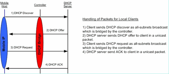
DHCP Bridging Mode
The DHCP bridging feature is designed to make the controller’s role in the DHCP transaction entirely transparent to the client. With the exception of 802.11 to Ethernet II conversion, packets from the client are bridged unmodified from the Light Weight Access Point Protocol (LWAPP) tunnel to the client’s VLAN (or Ethernet over IP (EoIP) tunnel in the L3 roaming case). Similarly, with the exception of Ethernet II to 802.11 conversion, packets to the client are bridged unmodified from the client’s VLAN (or EoIP tunnel in the L3 roaming case) to the LWAPP tunnel. Think of this as wiring a client into a switchport and then the client performs a traditional DHCP transaction.
Bridging Configuration Example
In order to enable the DHCP bridging functionality on the controller, you must disable the DHCP proxy feature on the controller. This can only be accomplished in the CLI with these commands:
(Cisco Controller) >config dhcp proxy disable
(Cisco Controller) >show dhcp proxy
DHCP Proxy Behaviour: disabled
If the DHCP server does not exist on the same Layer 2 (L2) network as the client then the broadcast will need to be forwarded to the DHCP server at the client gateway using an IP helper. This is a sample of this configuration:
Switch#conf t
Switch(config)#interface vlan <client vlan #>
Switch(config-if)#ip helper-address <dhcp server IP>
The DHCP bridging feature is a global setting, so it affects all DHCP transactions within the controller. You need to add IP helper statements in the wired infrastructure for all necessary VLANs on the controller.
DHCP with WLAN contrller
http://www.cisco.com/c/en/us/support/docs/wireless/4400-series-wireless-lan-controllers/110865-dhcp-wlc.html