When a large OSPF area is divided into smaller areas, this is called multiarea OSPF. Multiarea OSPF is useful in larger network deployments to reduce processing and memory overhead.
Multiarea OSPF requires a hierarchical network design. The main area is called the backbone area (area 0) and all other areas must connect to the backbone area.
Multiarea OSPF have these advantages:
- Smaller routing tables – There are fewer routing table entries as network addresses can be summarized between areas.
- Reduced frequency of SPF calculations – Localizes impact of a topology change within an area. For instance, it minimizes routing update impact, because LSA flooding stops at the area boundary.
- Reduced link-state update overhead – Minimizes processing and memory requirements, because there are fewer routers exchanging LSAs.
- Confines network instability to single areas of the network
two-layer area hierarchy:
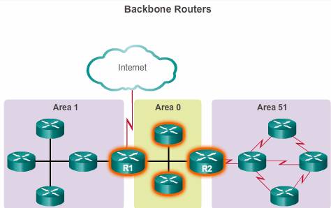
- Backbone (Transit) area – An OSPF area whose primary function is the fast and efficient movement of IP packets. Backbone areas interconnect with other OSPF area types. Generally, end users are not found within a backbone area. The backbone area is also called OSPF area 0. Hierarchical networking defines area 0 as the core to which all other areas directly connect.
- Regular (Non-backbone) area – Connects users and resources. Regular areas are usually set up along functional or geographical groupings. By default, a regular area does not allow traffic from another area to use its links to reach other areas. All traffic from other areas must cross a transit area.
Inter-area traffic: All traffic moving from one area to another area must traverse the backbone area. This traffic is referred to as inter-area traffic.
Cisco recommends the following guidelines:
- An area should have no more than 50 routers.
- A router should not be in more than three areas.
- Any single router should not have more than 60 neighbors.
There are four different types of OSPF routers:
- Internal router – This is a router that has all of its interfaces in the same area. All internal routers in an area have identical LSDBs.

- Backbone router – This is a router in the backbone area. Generally, the backbone area is set to area 0.
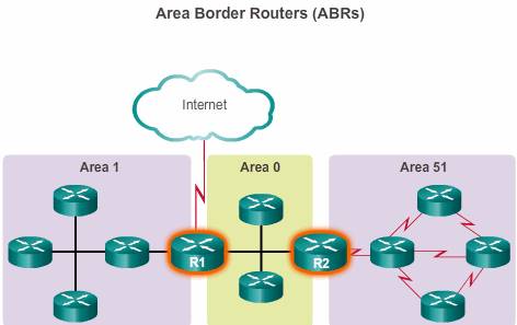
- Area Border Router (ABR) – This is a router that has interfaces attached to multiple areas. It must maintain separate LSDBs for each area it is connected to, and can route between areas. ABRs are exit points for the area, which means that routing information destined for another area can get there only via the ABR of the local area. ABRs can be configured to summarize the routing information from the LSDBs of their attached areas. ABRs distribute the routing information into the backbone. The backbone routers then forward the information to the other ABRs. In a multiarea network, an area can have one or more ABRs.
- Autonomous System Boundary Router (ASBR) – This is a router that has at least one interface attached to an external internetwork (another autonomous system), such as a non-OSPF network. An ASBR can import non-OSPF network information to the OSPF network, and vice versa, using a process called route redistribution.

Redistribution in multiarea OSPF occurs when an ASBR connects different routing domains (e.g., EIGRP and OSPF) and configures them to exchange and advertise routing information between those routing domains.
A router can be classified as more than one router type. For example, if a router connects to area 0 and area 1, and in addition, maintains routing information for another, non-OSPF network, it falls under three different classifications: a backbone router, an ABR, and an ASBR.
LSA operation
LSAs are the building blocks of the OSPF LSDB. Individually, they act as database records and provide specific OSPF network details. In combination, they describe the entire topology of an OSPF network or area.
Type 1.
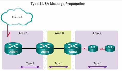
- All routers advertise their directly connected OSPF-enabled links in a type 1 LSA and forward their network information to OSPF neighbors. The LSA contains a list of the directly connected interfaces, link types, and link states.
- Type 1 LSAs are also referred to as router link entries.
- Type 1 LSAs are flooded only within the area in which they originated. ABRs subsequently advertise the networks learned from the type 1 LSAs to other areas as type 3 LSAs.
- The type 1 LSA link ID is identified by the router ID of the originating router.
Type 2
A type 2 LSA only exists for multiaccess and non-broadcast multiaccess (NBMA) networks where there is a DR elected and at least two routers on the multiaccess segment. The type 2 LSA contains the router ID and IP address of the DR, along with the router ID of all other routers on the multiaccess segment. A type 2 LSA is created for every multiaccess network in the area.
The purpose of a type 2 LSA is to give other routers information about multiaccess networks within the same area.
- Type 2 LSAs identify the routers and the network addresses of the multiaccess links
- Only a DR generates a type 2 LSA
- The DR floods type 2 LSAs only within the area in which they originated. Type 2 LSAs are not forwarded outside of an area.
- Type 2 LSAs are flooded within the multiaccess network and do not go beyond an ABR.
- A type 2 LSA link-state ID is identified by the DR router ID
Type 2 LSAs are also referred to as network link entries.
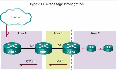
As shown in the figure, ABR1 is the DR for the Ethernet network in area 1. It generates the type 2 LSA and forwards it into area 1. ABR2 is the DR for the multiaccess network in area 0. There are no multiaccess networks in area 2 and therefore, no type 2 LSAs are ever propagated in that area.
The link-state ID for a network LSA is the IP interface address of the DR that advertises it.
Type 3
ABRs collect type 1 LSAs in the LSDB. After an OSPF area has converged, the ABR creates a type 3 LSA for each of its learned OSPF networks. Therefore, an ABR with many OSPF routes must create type 3 LSAs for each network.
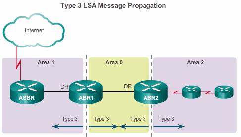
As shown in the figure, ABR1 and ABR2 floods type 3 LSAs from one area to other areas. The ABRs propagate the type 3 LSAs into other areas. In a large OSPF deployment with many networks, propagating type 3 LSAs can cause significant flooding problems. For this reason, it is strongly recommended that manual route summarization be configured on the ABR.
The link-state ID is set to the network number and the mask is also advertised.
Receiving a type 3 LSA into its area does not cause a router to run the SPF algorithm. The routes being advertised in the type 3 LSAs are appropriately added to or deleted from the router’s routing table, but a full SPF calculation is not necessary.
- A type 3 LSA describes a network address learned by type 1 LSAs.
- A type 3 LSA is required for every subnet.
- ABRs flood type 3 LSAs to other areas and are regenerated by other ABRs.
- A type 3 LSA link-state ID is identified by the network address.
- By default, routes are not summarized.
Type 4
Type 4 and type 5 LSAs are used collectively to identify an ASBR and advertise external networks into an OSPF routing domain.
A type 4 summary LSA is generated by an ABR only when an ASBR exists within an area. A type 4 LSA identifies the ASBR and provides a route to it. All traffic destined to an external autonomous system requires routing table knowledge of the ASBR that originated the external routes.
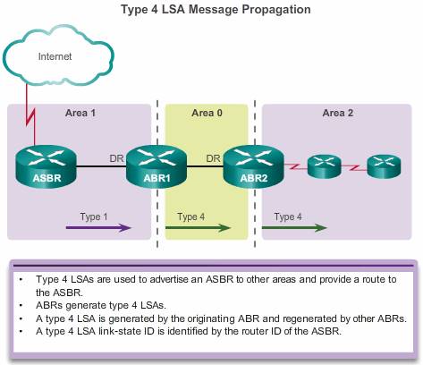
As shown in the figure, the ASBR sends a type 1 LSA, identifying itself as an ASBR. The LSA includes a special bit known as the external bit (e bit) that is used to identify the router as an ASBR. When ABR1 receives the type 1 LSA, it notices the e bit, it builds a type 4 LSA, and then floods the type 4 LSA to the backbone (area 0). Subsequent ABRs flood the type 4 LSA into other areas.
The link-state ID is set to the ASBR router ID.
- Type 4 LSAs are used to advertise an ASBR to other areas and provide a route to the ASBR.
- ABRs generate type 4 LSAs.
- A type 4 LSA is generated by the originating ABR and regenerated by other ABRs.
- A type 4 LSA link-state ID is identified by the router ID of the ASBR.
Type 5
Type 5 external LSAs describe routes to networks outside the OSPF autonomous system. Type 5 LSAs are originated by the ASBR and are flooded to the entire autonomous system.
Type 5 LSAs are also referred to as autonomous system external LSA entries.
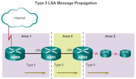
In the figure, the ASBR generates type 5 LSAs for each of its external routes and floods it into the area. Subsequent ABRs also flood the type 5 LSA into other areas. Routers in other areas use the information from the type 4 LSA to reach the external routes.
In a large OSPF deployment with many networks, propagating multiple type 5 LSAs can cause significant flooding problems. For this reason, it is strongly recommended that manual route summarization be configured on the ASBR.
The link-state ID is the external network number.
- Type 5 LSAs are used to advertise external (i.e., non-OSPF) network addresses.
- An ASBR generates a type 5 LSA.
- Type 5 LSAs are flooded throughout the area and regenerated by other ABRs.
- A type 5 LSA link-state ID is the external network address.
- By default, routes are not summarized.
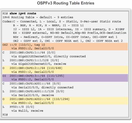
Routing table
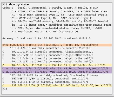
OSPF routes in an IPv4 routing table are identified using the following descriptors:
- O – Router (type 1) and network (type 2) LSAs describe the details within an area. The routing table reflects this link-state information with a designation of O, meaning that the route is intra-area.
- O IA – When an ABR receives summary LSAs, it adds them to its LSDB and regenerates them into the local area. When an ABR receives external LSAs, it adds them to its LSDB and floods them into the area. The internal routers then assimilate the information into their databases. Summary LSAs appear in the routing table as IA (interarea routes).
- O E1 or O E2 – External LSAs appear in the routing table marked as external type 1 (E1) or external type 2 (E2) routes.
 Route calculation
The order in which the best paths are calculated is as follows:
1. All routers calculate the best paths to destinations within their area (intra-area) and add these entries to the routing table. These are the type 1 and type 2 LSAs, which are noted in the routing table with a routing designator of O. (1)
2. All routers calculate the best paths to the other areas within the internetwork. These best paths are the interarea route entries, or type 3 and type 4 LSAs, and are noted with a routing designator of O IA. (2)
3. All routers (except those that are in a form of stub area) calculate the best paths to the external autonomous system (type 5) destinations. These are noted with either an O E1 or an O E2 route designator, depending on the configuration. (3)
When converged, a router can communicate with any network within or outside the OSPF autonomous system.