Ethernet frames do not have a time to live (TTL) attribute, like IP packets. As a result, if there is no mechanism enabled to block continued propagation of these frames on a switched network, they continue to propagate between switches endlessly, or until a link is disrupted and breaks the loop.
When multiple paths exist between two devices on a network, and there is no spanning tree implementation on the switches, a Layer 2 loop occurs, the issue of Layer 2 loop:
- MAC database instability – Instability in the content of the MAC address table results from copies of the same frame being received on different ports of the switch. Data forwarding can be impaired when the switch consumes the resources that are coping with instability in the MAC address table.
- Broadcast storms – Without some loop-avoidance process, each switch may flood broadcasts endlessly. This situation is commonly called a broadcast storm.
A broadcast storm occurs when there are so many broadcast frames caught in a Layer 2 loop that all available bandwidth is consumed. Consequently, no bandwidth is available for legitimate traffic and the network becomes unavailable for data communication. It is a form of DoS.
Because devices connected to a network are regularly sending out broadcast frames, such as ARP requests, a broadcast storm can develop in seconds. As a result, when a loop is created, the switched network is quickly brought down - Multiple frame transmission – Multiple copies of unicast frames may be delivered to destination stations. Many protocols expect to receive only a single copy of each transmission. Multiple copies of the same frame can cause unrecoverable errors.
Protocols that make use of a sequence-numbering mechanism assume that the transmission has failed and that the sequence number has recycled for another communication session.
Result:
This creates a high CPU load on all switches caught in the loop. Because the same frames are constantly being forwarded back and forth between all switches in the loop, the CPU of the switch must process a lot of data.
This slows down performance on the switch when legitimate traffic arrives.
Introduction
STP ensures that there is only one logical path between all destinations on the network by intentionally blocking redundant paths that could cause a loop.
A port is considered blocked when user data is prevented from entering or leaving that port. This does not include bridge protocol data unit (BPDU) frames that are used by STP to prevent loops. Blocking the redundant paths is critical to preventing loops on the network. The physical paths still exist to provide redundancy, but these paths are disabled to prevent the loops from occurring. If the path is ever needed to compensate for a network cable or switch failure, STP recalculates the paths and unblocks the necessary ports to allow the redundant path to become active.
Spanning tree instance
A spanning tree instance is created when the first interface is assigned to a VLAN and is removed when the last interface is moved to another VLAN. As well, you can configure STP switch and port parameters before a spanning tree instance is created. These parameters are applied when a spanning tree instance is created.
Naming
In order to communicate spanning tree concepts correctly, it is important to refer to the particular implementation or standard in context. The latest IEEE documentation on spanning tree, IEEE-802-1D-2004, says “STP has now been superseded by the Rapid Spanning Tree Protocol (RSTP)”; so one sees that the IEEE uses “STP” to refer to the original implementation of spanning tree and “RSTP” to describe the version of spanning tree specified in IEEE-802.1D-2004.
Note: STP is based on an algorithm invented by Radia Perlman.
Spanning Tree Algorithm (STA)
All switches participating in STP exchange BPDU frames to determine which switch has the lowest bridge ID (BID) on the network.
Note that in switch, all the lowest value will win the election, such as BID, Priority value in root bridge; MAC address, port number in the port role selection; and so forth. In the router, all the highest value will win the election, such as the Interface IP addresses in Router ID election; DR and BDR election; so forth.
http://www.cisco.com/image/gif/paws/10556/spanning_tree1.swf
Step1 The switch with the lowest BID automatically becomes the root bridge for the STA calculations.The root bridge serves as a reference point for all spanning tree calculations to determine which redundant paths to block.
Bridge Protocol Data Unit(BPDU): a messaging frame exchanged by switches for STP. Each BPDU contains a BID that identifies the switch that sent the BPDU.
All switches in the broadcast domain participate in the election process. After a switch boots, it begins to send out BPDU frames every two seconds. These BPDUs contain the switch BID and the root ID.
The BID contains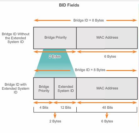
- Priority value(4bits, but forming 2 bytes with 12 bits of extended system ID): Priority is the initial deciding factor when electing a root bridge.
The default priority value for all Cisco switches is 32768. The range is 0 to 61440 in increments of 4096(the lower 12 bit is taken by extended system ID). Valid priority values are 0, 4096, 8192, 12288, 16384, 20480, 24576, 28672, 32768, 36864, 40960, 45056, 49152, 53248, 57344, and 61440. All other values are rejected. A bridge priority of 0 takes precedence over all other bridge priorities.
If the priorities of all the switches are the same, the device with the lowest MAC address becomes the root bridge. - An extended system ID( optional, 12 bits ) :
Early implementations of IEEE 802.1D were designed for networks that did not use VLANs. There was a single common spanning tree across all switches. For this reason, in older Cisco switches, the extended system ID could be omitted in BPDU frames.
As VLANs became common for network infrastructure segmentation, 802.1D was enhanced to include support for VLANs, requiring the VLAN ID to be included in the BPDU frame. VLAN information is included in the BPDU frame through the use of the extended system ID( equal to the VLAN number).
The extended system ID value is added to the bridge priority value in the BID to identify the priority and VLAN of the BPDU frame. - MAC address of the sending switch(6 bytes):
The MAC address with the lowest hexadecimal value is considered to be the preferred root bridge.
This MAC address can be any MAC address of an interface on the switch, no matter in up state or down state.
Initially, all switches are configured with the same default priority value. The MAC address is then the deciding factor on which switch is going to become the root bridge. To ensure that the root bridge decision best meets network requirements, it is recommended that the administrator configure the desired root bridge switch with a lower priority.The lowest BID value is determined by the combination of these three fields.
The Bridge ID field indicates the priority and MAC address ID of the bridge sending the message. This label allows the root bridge to identify where the BPDU originated, as well as for identifying the multiple paths from the switch to the root bridge. When the root bridge receives more than one BPDU from a switch with different path costs it knows that there are two distinct paths and uses the one path with the lower cost.
The Root ID indicates the root bridge by listing its 2-byte priority followed by its 6-byte MAC address ID. When a switch first boots, the root ID is the same as the bridge ID. However, as the election process occurs, the lowest bridge ID replaces the local root ID to identify the root bridge switch.
If the root ID from a BPDU received is lower than the root ID on the receiving switch, then the receiving switch updates its root ID, identifying the adjacent switch as the root bridge. Actually, it may not be an adjacent switch, but could be any other switch in the broadcast domain. The switch then forwards new BPDU frames with the lower root ID to the other adjacent switches. Eventually, the switch with the lowest BID ends up being identified as the root bridge for the spanning tree instance.
One root bridge per spanning tree instance. It is possible to have multiple distinct root bridges for different spanning tree instances. If all ports on all switches are members of VLAN 1, then there is only one spanning tree instance. The extended system ID plays a role in how spanning tree instances are determined.
Step 2. The STA considers both path and port costs when determining which ports to block.
The default port costs are defined by the speed at which the port operates.10Gbps port cost is 2, 1 Gbps is 4, etc.
The path information is determined by summing up the individual port costs along the path from the destination to the root bridge. Each “destination” is actually a switch port.
- The path costs are calculated using port cost values associated with port speeds for each switch port along a given path.
- The sum of the port cost values determines the overall path cost to the root bridge. If there is more than one path to choose from, STA chooses the path with the lowest path cost.
Step 3 When the STA has determined which paths are most desirable relative to each switch, it assigns port roles to the participating switch ports.

- Root ports – Switch ports closest to the root bridge. Root ports are selected on a per-switch basis. One root port per non-root bridge.
- Designated ports – All non-root ports that are still permitted to forward traffic on the network. Designated ports are selected on a per-trunk basis.
If one end of a trunk is a root port, then the other end is a designated port. All ports on the root bridge are designated ports. One designated port per segment.
- Alternate and backup ports – Alternate ports and backup ports are configured to be in a blocking state to prevent loops. Alternate ports are selected only on trunk links where neither end is a root port. This allows for faster transition to a forwarding state, when necessary. (Blocking ports only come into play when two ports on the same switch provide redundant links through the network.)
- Disabled ports( non-designated ports) – A disabled port is a switch port that is shut down.
Steps to select the port roles ( from the ports which are closest to the root bridge to the ports which are most far away from the root bridge)
1. All the ports on the root bridge are designated ports
2. Every non-root bridge must select one Root Port. One segment has one root port, so the ports which is on the opposite of the designated ports (selected in step1) will be root ports.
3. Non-root bridges select their respective root port based on the Root path cost, which is the cumulative cost of all links to the root bridge.
4. If there is a tie in two bridge, the lower bridge ID switch will be the Designated Port.
5. If a port is neither designated port nor root port, then the port will be turned into disabled state.
BPDU Frame Format
A BPDU frame contains 12 distinct fields that convey path and priority information used to determine the root bridge and paths to the root bridge.
- The first four fields identify the protocol, version, message type, and status flags.
- The Protocol ID field indicates the type of protocol being used. This field contains the value zero.
- The Version field indicates the version of the protocol. This field contains the value zero.
- The Message type field indicates the type of message. This field contains the value zero.
- The Flags field includes one of the following:
Topology change (TC) bit, which signals a topology change in the event a path to the root bridge has been disrupted.
Topology change acknowledgment (TCA) bit, which is set to acknowledge receipt of a configuration message with the TC bit set.
- The next four fields are used to identify the root bridge and the cost of the path to the root bridge.
- The Root ID field indicates the 2-byte priority followed by its 6-byte MAC address ID of the root bridge . When a switch first boots, the root ID is the same as the bridge ID(Each switch in the broadcast domain initially assumes that it is the root bridge for a spanning tree instance). However, as the election process occurs, the lowest bridge ID replaces the local root ID to identify the root bridge switch.
- The Cost of path field indicates the cost of the path from the bridge sending the configuration message to the root bridge. The path cost field is updated by each switch along the path to the root bridge.
- The Bridge ID field indicates the priority and MAC address ID of the bridge sending the message. This label allows the root bridge to identify where the BPDU originated, as well as for identifying the multiple paths from the switch to the root bridge. When the root bridge receives more than one BPDU from a switch with different path costs it knows that there are two distinct paths and uses the one path with the lower cost.
- The Port ID field indicates the port number from which the configuration message was sent. This field allows loops created by multiple attached bridges to be detected and corrected.
- The last four fields are all timer fields that determine how frequently BPDU messages are sent and how long the information received through the BPDU process is retained
- Message Age: The Message age field indicates the amount of time that has elapsed since the root sent the configuration message on which the current configuration message is based.
- The Max age field indicates when the current configuration message should be deleted. Once the message age reaches the maximum age, the switch expires the current configuration and initiates a new election to determine a new root bridge since it assumes that it has been disconnected from the root bridge. This is 20 seconds by default, but can be tuned to be between 6 and 40 seconds.
- The Hello time field indicates the time between root bridge configuration messages. The interval defines how long the root bridge waits between sending configuration message BPDUs. This is equal to 2 seconds by default, but can be tuned to be between 1 and 10 seconds.
- The Forward delay field indicates the length of time that bridges should wait before transitioning to a new state after a topology change. If a bridge transitions too soon, it is possible that not all network links will be ready to change their state and loops can result. This is by default equal to 15 seconds for each state, but can be tuned to be between 4 and 30 seconds.