Cisco Express Forwarding
Note Many people have a challenge with the term packet switching, because they are accustomed to switching being a Layer 2 operation, while routing is a Layer 3 operation. The key to understanding this term is to think of frame switching being a Layer 2 operation, while packet switching (the same thing as routing) is a Layer 3 operation.
Much of the literature on router architecture divides router functions into three operational planes:
- Management plane: The management plane is concerned with the management of the device. For example, an administrator connecting to a router through a Secure Shell (SSH) connection through one of the router’s VTY lines would be a management plane operation.
- Control plane: The control plane is concerned with making packet-forwarding decisions. For example, routing protocol operation would be a control plane function.
- Data plane: The data plane is concerned with the forwarding of data through a router. For example, end-user traffic traveling from a user’s PC to a web server on a different network would go across the data plane.
Cisco routers support the following three primary modes of packet switching:
- Process switching
Operation of Process Switching
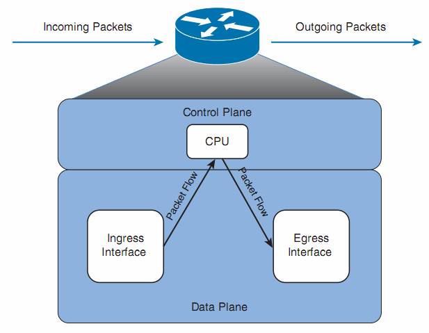
When a router routes a packet (that is, performs packet switching), the router removes the packet’s Layer 2 header, examines the Layer 3 addressing, and decides how to forward the packet. The Layer 2 header is then rewritten (which might involve changing the source and destination MAC addresses and computing a new cyclic redundancy check [CRC]), and the packet is forwarded out an appropriate interface. With process switching, as illustrated in Figure above , a router’s CPU becomes directly involved with packet-switching decisions. As a result, the performance of a router configured for process switching can suffer significantly.
Configuration:
An interface can be configured for process switching by disabling fast switching on that interface. The interface configuration mode command used to disable fast switching isno ip route-cache. - Fast switching
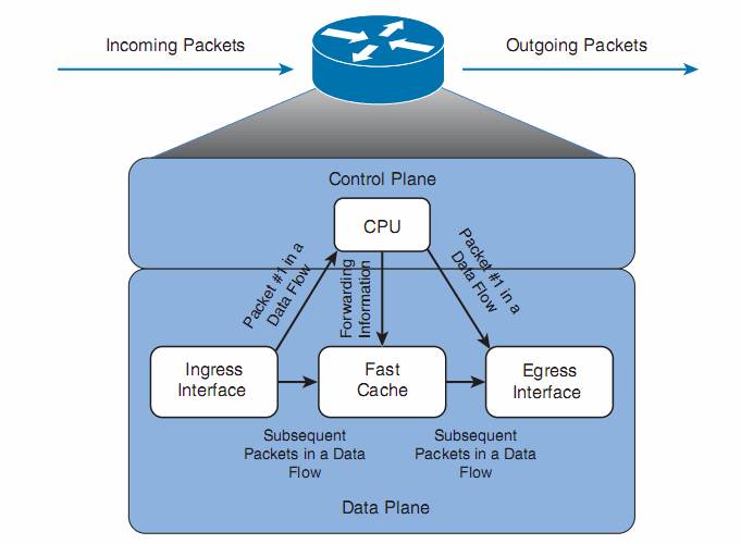
Fast switching uses a fast cache maintained in a router’s data plane. The fast cache contains information about how traffic from different data flows should be forwarded. As seen in Figure above , the first packet in a data flow is process switched by a router’s CPU. After the router determines how to forward the first frame of a data flow, the forwarding information is stored in the fast cache. Subsequent packets in that same data flow are forwarded based on information in the fast cache, as opposed to being process switched.
As a result, fast switching dramatically reduces a router’s CPU utilization, as compared to process switching.
Configuration:
Fast switching can be configured in interface configuration mode with the commandip route-cache. - Cisco Express Forwarding (CEF)
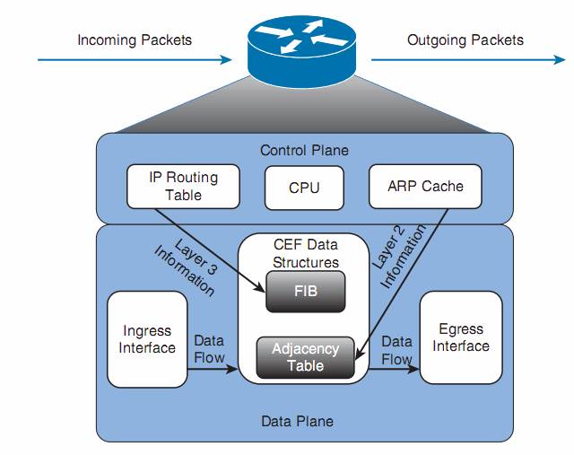
Cisco Express Forwarding (CEF) maintains two tables in the data plane. Specifically, the Forwarding Information Base (FIB) maintains Layer 3 forwarding information, whereas the adjacency table maintains Layer 2 information for next hops listed in the FIB.
Using these tables, populated from a router’s IP routing table and ARP cache, CEF can efficiently make forwarding decisions. Unlike fast switching, CEF does not require the first packet of a data flow to be process switched. Rather, an entire data flow can be forwarded at the data plane, as seen in Figure .
On many router platforms, CEF is enabled by default. If it is not, you can globally enable it with the ip cef command. Alternately, if CEF is enabled globally but is not enabled on a specific interface, you can enable it on that interface with the interface configuration mode command ip route-cache cef .
configuration and verification commands for CEF:
| Command | Description |
| router(config)# ip cef | globally enable CEF |
| router(config-if)# ip route-cache cef | Enables CEF on an interface (if CEF is globally enabled), in interface configuration mode. |
| show ip interface interface-id | Displays multiple interface statistics, including information about an interface’s packet-switching mode. |
| show ip cef | Displays the contents of a router’s FIB. |
| show adjacency [ detail ] | Provides information contained in the adjacency table of a router, including protocol and timer information. |
Policy Based Routing
Routing without PBR:
When a packet arrives at the incoming interface of a router, the router’s data plane processing logic takes several steps to process the packet.
- The incoming packet actually arrives encapsulated inside a data link layer frame, so the router must check the incoming frame’s Frame Check Sequence (FCS) and discard the frame if errors occurred in transmission.
- If the FCS check passes, the router discards the incoming frame’s data-link header and trailer, leaving the Layer 3 packet.
- Finally, the router does the equivalent of comparing the destination IP address of the packet with the IP routing table, matching
the longest-prefix route that matches the destination IP address.
Policy-Based Routing (PBR) overrides a router’s natural destination-based forwarding logic. PBR intercepts the packet after de-encapsulation on the incoming interface, before router performs the CEF table lookup. PBR then chooses how to forward the packet using criteria other than the usual matching of the packet’s destination address with the CEF table.
PBR chooses how to forward the packet by using matching logic defined through a route map.
Two general steps to configure:
Step 1. Create a route map with the logic to match packets, and choose the route.
To match packets with a route map enabled for PBR, you use the route-map match command. However, you have two match command options to use:
- match ip address
- match length min max , allows you to specify a range of lengths, in bytes
When a route map clause (with a permit action) matches a packet, the set command defines the action to take regarding how to forward the packet. The four set command options define either the outgoing interface or the next-hop IP address:
| Command | Comments |
| set ip next-hop ip-address [ …ip-address ] | Next-hop addresses must be in a connected subnet; PBR forwards to the first address in the list for which the associated interface is up. |
| set ip default next-hop ip-address [ …ip-address ] | Same logic as previous command, except PBR first attempts to route based on the routing table. |
| set interface interface-type interface-number [ …interface-type interface-number ] | PBR forwards packets using the first interface in the list that is up. |
| set default interface interface-type interface- number [ …interface-type interface-number ] | Same logic as previous command, except PBR first attempts to route based on the routing table. |
Note that two of the commands allow the definition of a next-hop router, and two allow the definition of an outgoing interface. The other difference in the commands relates to whether the command includes the default keyword.
Default keyword:
This parameter in effect tells Cisco IOS whether to apply PBR logic before trying to use normal routing, or whether to first try to use the normal routing, relying on PBR’s logic only if the destination-based routing logic fails to match a nondefault route.
- Omitting the default parameter gives you logic like this: “Try PBR first, and if PBR’s route does not work, try to route as usual.”The router basically use this sequence: PBR > normal routing > default route (last resort)
- Including the default parameter gives you logic like this: “Try to route as usual while ignoring any default routes, but if normal routing fails, use PBR.”The router basically use this sequence: normal routing > PBR > default route
Step 2. Enable the route map for use with PBR, on an interface, for packets entering the interface.
router(config-if)# ip policy route-map name
Example:
router(config)# access-list 101 permit ip host 10.1.1.2 10.1.3.0 0.0.0.255
router(config)#route-map PC2-over-low-route permit
router(config-route-map)#match ip address 101
router(config-route-map)#set ip next-hop 10.1.14.4router(config)# interface Fastethernet 0/0
router(config-if)#ip address 10.1.1.9 255.255.255.0
router(config-if)#ip policy route-map PC2-over-low-route
PBR processes packets that match a permit clause in the ACL using the defined set command. For packets matched by a deny clause, PBR lets the packet go through to the normal IP routing process.
Verify
- The
show ip policycommand just shows the interfaces on which PBR is enabled and the route map used. - The
show route-mapcommand shows overall statistics for the number of packets matching the route map for PBR purposes. - The only way to verify the types of packets that are policy routed is to use the
debug ip policycommand, which can produce excessive overhead on production routers, given its multiple lines of output per packet, or to use traceroute.
Applying PBR to Locally Created Packets
In some cases, it might be useful to use PBR to process packets generated by the router itself. However, PBR normally processes packets that enter the interface(s) on which the ip policy route-map command has been configured, and packets generated by the router itself do not actually enter the router through some interface.
To make Cisco IOS process locally created packets using PBR logic, configure the ip local policy route-map name global command, referring to the PBR route map at the end of the command.
Setting IP precedence
Quality of service (QoS) refers to the entire process of how a network infrastructure can choose to apply different levels of service to different packets.
Type of service (ToS) byte in IP header. The IP header originally defined a ToS byte whose individual bits have been defined in a couple of ways over the years. One such definition used the three leftmost bits in the ToS byte as a 3-bit IP Precedence (IPP) field, which could be used for generic QoS marking, with higher values generally implying a better QoS treatment.
PBR supports setting the older QoS marking fields—the IP Precedence (IPP) and the entire ToS byte—using the commands set ip precedence value and set ip tos value , respectively, in a route map. To configure packet marking, configure PBR as normal, but add a set command that defines the field to be marked and the value.