IP service Level Agreement
The Cisco IOS IP Service-Level Agreement (IP SLA) feature measures the ongoing behavior of the network. The measurement can be as simple as using the equivalent of a ping to determine whether an IP address responds, or as sophisticated as measuring the jitter (delay variation) of VoIP packets that flow over a particular path.
To use IP SLA, an engineer configures IP SLA operations on various routers, and the routers will then send packets, receive responses, and gather data about whether a response was received, and the specific characteristics of the results, such as delay and jitter measurements.
The routers gather the results of the operations, storing the statistics in the CISCO-RTTMON-MIB.
SLA concepts
IP SLA uses the concept of an operation . Each operation defines a type of packet that the router will generate, the destination and source address, and other characteristics of the packet.
The configuration includes settings about
- the time of day when the router should be sending the packets in a particular operation,
- the types of statistics that should be gathered,
- how often the router should send the packets.
Note : Cisco IP SLA has origins in earlier Cisco IOS features, including the Response Time Reporter (RTR) feature. The RTR feature is configured with the rtr
command and uses the term probe to refer to what IP SLA refers to as an operation.
SLA operation
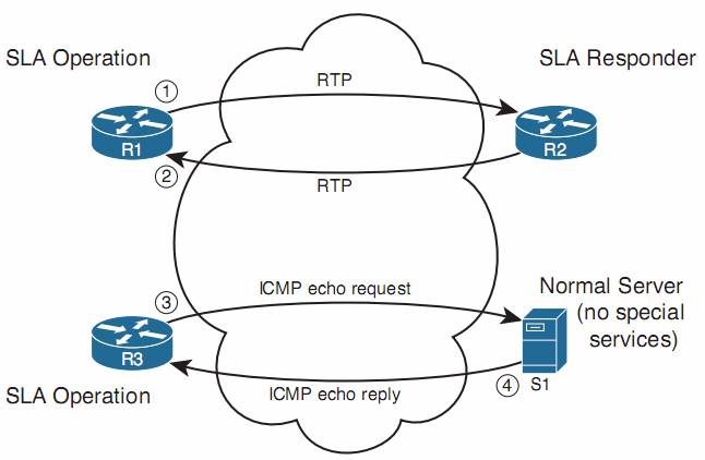
For the top half:
IP SLA supports the concept of the IP SLA responder, for R2. By configuring R2 as an IP SLA responder, it responds to packets that a router would not normally respond to, giving the network engineer a way to monitor network behavior without having to place devices around the network just to test the network.
For the bottom half:
An IP SLA operation can cause the router to send packets to any IP address, whether on a router or a host. When sending to a host, as seen in the bottom part of the figure, the host does not need any special software or configuration—instead, the host just acts as normal. That means that if an SLA operation sends packets to a host, the router can only use operation types that send packets that the host understands (eg.ICMP).
A wide range of IP SLA operations exist. The following list summarizes the majority of the available operation types, just for perspective:
- ICMP (echo, jitter)
- RTP (VoIP)
- TCP connection (establishes TCP connections)
- UDP (echo, jitter)
- DNS
- DHCP
- HTTP
- FTP
Configure IP SLA
Step 1. Create the IP SLA operation and assign it an integer operation number, using the global configuration command:
ip sla sla-ops-number
removing the operation with the :
no ip sla sla-ops-number
Step 2. Define the operation type and the parameters for that operation type. For ICMP echo, you define the destination IP address or host name, and optionally, the source IP address or host name, using the SLA operation subcommand:
icmp-echo { destination-ip-address | destination-hostname } [ source-ip { ip-address | hostname } | source-interface interface-name ]
Step 3. (Optional) Define a (nondefault) frequency at which the operation should send the packets, in seconds, using the IP SLA subcommand frequency seconds .
Step 4. Schedule when the SLA will run, using the global configuration command:
ip sla schedule sla-ops-number [ life { forever | seconds }] [ start-time { hh : mm [ : ss ] [ month day | day month ] | pending | now | after hh : mm : ss }] [ ageout seconds ] [ recurring ]
Verify
- show ip sla configuration : confirms all the configuration settings for the operation
- show ip sla statistics: lists the current statistics for the operation.
SLA configuration on ios12.4
http://www.cisco.com/c/en/us/td/docs/ios/12_4/ip_sla/configuration/guide/hsla_c/hsicmp.html
set ip next-hop with track command :
Example:Using Object Tracking

The following configuration sample shows a configuration used to track an object:

! Configure the objects to be tracked.

! Object 123 will be up if the router can ping 10.1.1.1.

! Object 124 will be up if the router can ping 10.2.2.2.

ip sla monitor 1

 type echo protocol ipicmpecho 10.1.1.1

ip sla monitor schedule 1 start-time now life forever

!

ip sla monitor 2

 type echo protocol ipicmpecho 10.2.2.2

ip sla monitor schedule 2 start-time now life forever

!

track 123 rtr 1 reachability

track 124 rtr 2 reachability

!

! Enable policy routing using route-map alpha on Ethernet 0.

interface ethernet 0

 ip address 10.4.4.254 255.255.255.0

 ip policy route-map alpha

!

! 10.1.1.1 is via this interface

interface ethernet 1

 ip address 10.1.1.254 255.255.255.0


! 10.2.2.2 is via this interface

interface ethernet 2

 ip address 10.2.2.254 255.255.255.0

!

! Configure a route-map to set the next-hop to 10.1.1.1 if object 123 is up. If object 123

! is down, the next hop will be set to 10.2.2.2 if object 124 is up. If object 124 is also

! down, then policy routing fails and unicast routing will route the packet.

route-map alpha

 set ip next-hop verify-availability 10.1.1.1 10 track 123

 set ip next-hop verify-availability 10.2.2.2 20 track 124
http://www.cisco.com/c/en/us/td/docs/ios/iproute_pi/command/reference/iri_book/iri_pi2.html
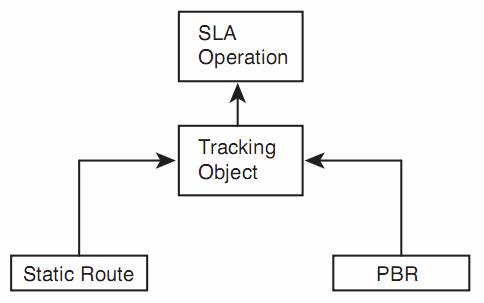
Tracking SLA Operations to Influence Routing
As previously mentioned, you can configure both static routes and PBR to be used only when an SLA operation remains successful. The configuration to achieve this logic requires the configuration of a tracking object and cross-references between the static route, PBR, and IP SLA.
 The tracking object looks at the IP SLA operation’s most recent return code to then determine the tracking state as either “up” or “down.” Depending on the type of SLA operation, the return code can be a simple toggle, with “OK” meaning that the last operation worked. The tracking object would then result in an “up” state if the SLA operation resulted in an “OK” return code.
One of the main reasons that Cisco IOS requires the use of this tracking object is to prevent flapping routes. Route flapping occurs when a router adds a route to its routing table then quickly removes it, conditions change causing the route to be added back to the table again, and so on. If a static route tracked an IP SLA object directly, the SLA object’s return code could change each time the operation ran, causing a route flap. The tracking object concept provides the ability to set a delay of how soon after a tracking state change the tracking object should change state. This feature gives the engineer a tool to control route flaps.
Configuring a Static Route to Track an IP SLA Operation
To configure a static route to track an IP SLA, you need to configure the tracking object and then configure the static route with the track keyword.
To do so, use these steps:
Step 1. Use the global command track object-number ip sla sla-ops-number [state | reachability ].
Step 2. (Optional) Configure the delay to regulate flapping of the tracking state by using the delay {down seconds | up seconds } command in tracking configuration mode.
Step 3. Configure the static route with the in global configuration mode command:
ip route destination mask {interface | next-hop} track object-number
Verify
- show track : It lists the current tracking state, the time in this state, the number of state transitions, and the other entities that track the object .
Configure PBR to track an IP SLA
Before, we use the command like: set ip next-hop 10.1.14.4
Instead, use the verify-availability keyword, as shown in this command:
set ip next-hop verify-availability 10.1.14.4 1 track 2
When the tracking object is up, PBR works as configured. When the tracking object is down, PBR acts as if the set command does not exist. That means that the router will still attempt to route the packet per the normal destination-based routing process.
VRF-lite
Service providers often need to allow their customers’ traffic to pass through their cloud without one customer’s traffic (and corresponding routes) exposed to another customer. Similarly, enterprise networks might need to segregate various application types, such as keeping voice and video traffic separate from data. These are just a couple of scenarios that could benefit from the Cisco Virtual Routing and Forwarding (VRF) feature.
VRF allows a single physical router to host multiple virtual routers, with those virtual routers logically isolated from one another, each with its own IP routing table.
If you want to send traffic for multiple virtual networks (that is, multiple VRFs) between two routers, you need to create a subinterface for each VRF.
However, with Cisco EVN, you instead create a trunk (called a Virtual Network (VNET) trunk ) between the routers. Then, traffic for multiple virtual networks can travel over that single trunk interface, which uses tags to identify the virtual networks to which packets belong.
VRF configuration
| Command | Description |
| ip vrf vrf-name | A global configuration mode command that creates a VRF and enters VRF configuration mode. |
| ip vrf forwarding vrf-name | An interface or subinterface configuration mode command that assigns an interface or a subinterface to a VRF instance. (Note: If the interface or subinterface already had an IP address assigned, this command will remove that address, and you will need to add it back.) |
| router ospf process-id vrf vrf-name | A global configuration mode command that associates a unique process ID with a VRF instance and enters OSPF router configuration mode for a specific VRF instance. (Note: When in OSPF router configuration mode, you can enter the OSPF commands that you would normally enter in this mode.) |
example:
ip vrf VOICE
!
ip vrf DATA
!
ip vrf VIDEO
!
… OUTPUT OMITTED…
!
interface FastEthernet0/0
no ip address
!
interface FastEthernet0/0.2
encapsulation dot1Q 2
ip vrf forwarding VOICE
ip address 192.0.2.1 255.255.255.252
!
interface FastEthernet0/0.3
encapsulation dot1Q 3
ip vrf forwarding DATA
ip address 198.51.100.1 255.255.255.252
!
interface FastEthernet0/0.4
encapsulation dot1Q 4ip vrf forwarding VIDEO
ip address 203.0.113.1 255.255.255.252
!
… OUTPUT OMITTED…
!
router ospf 1 vrf VOICE
network 0.0.0.0 255.255.255.255 area 0
!
router ospf 2 vrf DATA
network 0.0.0.0 255.255.255.255 area 0
!
router ospf 3 vrf VIDEO
network 0.0.0.0 255.255.255.255 area 0
keep in mind that even though different VRFs can have overlapping network addresses (because the VRF’s IP routing tables are logically separated), the OSPF
process ID needs to be unique for each VRF.
Verify
- show ip vrf : list a router’s VRFs, along with the interfaces assigned to each VRF.
- show ip route vrf vrf-name: view the contents of a specific VRF’s IP routing table.
- ping vrf vrf-name destination-ip : same function as ping.