Why Frame relay
Disadvantage of Leased line
- fixed capacity, which lead to capacity wastage.
- Needs a separate physical interface on the router, which increases equipment costs.
- Any change to the leased line generally requires a site visit by the carrier personnel.
- A dedicated line provides little practical opportunity for a one-to-many connection.
- The leased-line design also limits flexibility.
Frame relay
SPAN’s Frame Relay network uses Permanent Virtual Circuits (PVCs), A PVC is the logical path along an originating Frame Relay link, through the network, and along a terminating Frame Relay link to its ultimate destination.
- Configuring user equipment in a Frame Relay network is very simple. Frame Relay connections are created by configuring customer premise equipment (CPE) routers or other devices to communicate with a service provider Frame Relay switch.
- Cost effectiveness and flexibility: In Frame Relay, the end of each connection has a number to identify it called a Data Link Connection Identifier (DLCI). Any station can connect with any other simply by stating the address of that station and DLCI number of the line it must use. In a later section, you will learn that when Frame Relay is configured, all data from all configured DLCIs flows through the same port of the router.
Frame Relay operation
Virtual circuit:
There are two ways to establish VCs:
- Switched Virtual Circuits (SVC) – Established dynamically by sending signaling messages to the network (CALL SETUP, DATA TRANSFER, IDLE, CALL TERMINATION).
- Permanent Virtual Circuits (PVCs) – preconfigured by the carrier, and after they are set up, only operate in DATA TRANSFER and IDLE modes. Note that some publications refer to PVCs as private VCs. Permanent virtual circuits eliminate the need for repeated call set-up and clearing.
VCs provide a bidirectional communication path from one device to another. VCs are identified by DLCIs. DLCI values typically are assigned by the Frame Relay service provider. Frame Relay DLCIs have local significance, which means that the values themselves are not unique in the Frame Relay WAN. A DLCI identifies a VC to the equipment at an endpoint. A DLCI has no significance beyond the single link. Two devices connected by a VC may use a different DLCI value to refer to the same connection.
Locally significant DLCIs have become the primary method of addressing. Local addressing prevents a customer from running out of DLCIs as the network grows.
DLCIs 0 to 15 and 1,008 to 1,023 are reserved. Therefore, service providers typically assign DLCIs in the range of 16 to 1,007.
Multiple circuit:
Frame Relay is statistically multiplexed, meaning that it transmits only one frame at a time, but that many logical connections can co-exist on a single physical line. The Frame Relay Access Device (FRAD), or router connected to the Frame Relay network, may have multiple VCs connecting it to various endpoints. Keep in mind that the DLCI has only local significance and may be different at each end of a VC.
Cost Benefits of Multiple VCs
With Frame Relay, customers pay for the bandwidth they use. In effect, they pay for a Frame Relay port. When the customer increases the number of ports, as described above, they pay for more bandwidth, but they do not pay for more equipment because the ports are virtual. There is no change to the physical infrastructure.
Encapsulation
Frame Relay takes data packets from a network layer(not data link layer,do not confused with the name) protocol, such as IPv4 or IPv6, encapsulates them as the data portion of a Frame Relay frame, and then passes the frame to the physical layer for delivery on the wire.
First, Frame Relay accepts a packet from a network layer protocol, such as IPv4. It then wraps it with an address field that contains the DLCI and a checksum. Flag fields are added to indicate the beginning and end of the frame. The flag fields mark the start and end of the frame and are always the same. The flags are represented either as the hexadecimal number 7E or as the binary number 01111110. After the packet is encapsulated, Frame Relay passes the frame to the physical layer for transport.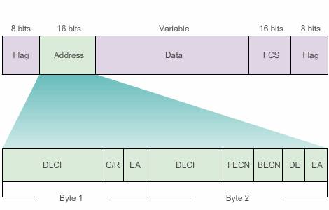
The CPE router encapsulates each Layer 3 packet inside a Frame Relay header and trailer before sending it across the VC.
The header and trailer are defined by the Link Access Procedure for Frame Relay (LAPF) Bearer Services specification, ITU Q.922-A. As shown in Figure above, the Frame Relay header (address field) specifically contains the following:
- DLCI – The 10-bit DLCI is one of the most important fields in the Frame Relay header. This value represents the virtual connection between the DTE device and the switch. Each virtual connection that is multiplexed on to the physical channel is represented by a unique DLCI. The DLCI values have local significance only, which means that they are unique only to the physical channel on which they reside. Therefore, devices at opposite ends of a connection can use different DLCI values to refer to the same virtual connection. The DLCI in the Byte 1 is the destination DLCI, the DLCI i nthe byte 2 is the source DLCI.
- C/R – The bit that follows the most significant DLCI byte in the Address field. The C/R bit is not currently defined.
- Extended Address (EA) – If the value of the EA field is 1, the current byte is determined to be the last DLCI octet. Although current Frame Relay implementations all use a two-octet DLCI, this capability does allow longer DLCIs in the future. The eighth bit of each byte of the Address field indicates the EA.
- Congestion Control – Consists of three Frame Relay congestion-notification bits. These three bits are specifically referred to as the Forward Explicit Congestion Notification (FECN), Backward Explicit Congestion Notification (BECN), and Discard Eligible(DE) bits.
The physical layer is typically EIA/TIA-232, 449 or 530, V.35, or X.21.
The Frame Relay frame is a subset of the HDLC frame type; therefore, it is delimited with flag fields. The FCS determines whether any errors in the Layer 2 address field occurred during transmission. The FCS is calculated prior to transmission by the sending node, and the result is inserted in the FCS field.
At the distant end, a second FCS value is calculated and compared to the FCS in the frame.If the results are the same, the frame is processed. If there is a difference, the frame is discarded. Frame Relay does not notify the source when a frame is discarded. Error control is left to the upper layers of the OSI model, so frame relay does not provide error control mechanism.
Topology
However, every network or network segment can be viewed as being one of three topology types: star, full mesh, or partial mesh.
Star Topology (Hub and Spoke)
The simplest WAN topology is a star.
In a star topology, the location of the hub is usually chosen by the lowest leased-line cost. When implementing a star topology with Frame Relay, each remote site has an access link to the Frame Relay cloud with a single VC.
One or more DLCI numbers are assigned to each line endpoint. Because Frame Relay costs are not distance-related, the hub does not need to be in the geographical center of the network.
Full Mesh Topology
A full mesh topology suits a situation in which the services to be accessed are geographically dispersed and highly reliable access to them is required.

Using Frame Relay Mesh, a network designer can build multiple connections simply by configuring additional VCs on each existing link, as shown in Figure. This software upgrade grows the star topology to a full mesh topology without the expense of additional hardware or dedicated lines. Because VCs use statistical multiplexing, multiple VCs on an access link generally make better use of Frame Relay than single VCs.
Service providers will charge for the additional bandwidth, but this solution is usually more cost effective than using dedicated lines.
Partial Mesh Topology
For large networks, a full mesh topology is seldom affordable because the number of links required increases exponentially. The issue is not with the cost of the hardware, but because there is a theoretical limit of less than 1,000 VCs per link. In practice, the limit is less than that.
For this reason, larger networks are generally configured in a partial mesh topology. With partial mesh, there are more interconnections than required for a star arrangement, but not as many as for a full mesh. The actual pattern is dependent on the data flow requirements.
Address Mapping
Cisco routers support all network layer protocols over Frame Relay, such as IPv4, IPv6, IPX, and AppleTalk. This address-to-DLCI mapping can be accomplished either by static or dynamic mapping. Figure 1 shows an example topology with DLCI mapping.

Inverse ARP
A primary tool of Frame Relay is Inverse Address Resolution Protocol (ARP). Whereas ARP translates Layer 3 IPv4 addresses to Layer 2 MAC addresses, Inverse ARP does the opposite, translate layer 2 DLCI to layer 3 IP address. The corresponding Layer 3 IPv4 addresses must be available before VCs can be used.
Note: Frame Relay for IPv6 uses Inverse Neighbor Discovery (IND) to obtain a Layer 3 IPv6 address from a Layer 2 DLCI. A Frame Relay router sends an IND Solicitation message to request a Layer 3 IPv6 address corresponding to a Layer 2 DLCI address of the remote Frame Relay router. At the same time the IND Solicitation message provides the sender’s Layer 2 DLCI address to the remote Frame Relay router.
Dynamic Mapping
Dynamic address mapping relies on Inverse ARP to resolve a next-hop network layer IPv4 address to a local DLCI value.
The Frame Relay router sends out Inverse ARP requests on its PVC to discover the protocol address of the remote device connected to the Frame Relay network. The router uses the responses to populate an address-to-DLCI mapping table on the Frame Relay router or access server. The router builds and maintains this mapping table, which contains all resolved Inverse ARP requests.
Static Frame Relay Mapping
The user can choose to override dynamic Inverse ARP mapping by supplying a manual static map for the next-hop protocol address to a local DLCI. A static map works similarly to dynamic Inverse ARP by associating a specified next-hop protocol address to a local Frame Relay DLCI. You cannot use Inverse ARP and a map statement for the same DLCI and protocol.
- An example of using static address mapping is a situation in which the router at the other side of the Frame Relay network does not support dynamic Inverse ARP for a specific network protocol.
- Another example is on a hub-and-spoke Frame Relay network. Use static address mapping on the spoke routers to provide spoke-to-spoke reachability. Because the spoke routers do not have direct connectivity with each other, dynamic Inverse ARP would not work between them. Dynamic Inverse ARP relies on the presence of a direct point-to-point connection between two ends. In this case, dynamic Inverse ARP only works between hub and spoke, and the spokes require static mapping to provide reachability to each other.
Configuring Static Mapping
Establishing static mapping depends on your network needs. To map between a next hop protocol address and DLCI destination address, use this command:
frame-relay map protocol protocol-address dlci [broadcast] [ietf] [cisco]
Eg. R1(config-if)# frame-relay map ip 10.1.1.2 102 broadcast cisco
- Protocol: typically ip.
- Use the keyword ietf when connecting to a non-Cisco router.
- The configuration of Open Shortest Path First (OSPF) protocol can be greatly simplified by adding the optional broadcast keyword when doing this task.
The broadcast keyword specifies that broadcast and multicast traffic is allowed over the VC. This configuration permits the use of dynamic routing protocols over the VC!!. If you miss the “broadcast” keyword, the routers running eigrp will have adjacency problem:Some message like this:*Jun 26 20:28:13.673: %DUAL-5-NBRCHANGE: EIGRP-IPv4 1: Neighbor 10.1.1.2 (Serial0/0/0) is up: new adjacency
R1(config-if)#
*Jun 26 20:31:18.185: %DUAL-5-NBRCHANGE: EIGRP-IPv4 1: Neighbor 10.1.1.2 (Serial0/0/0) is down: retry limit exceeded
R1(config-if)#
*Jun 26 20:32:00.977: %DUAL-5-NBRCHANGE: EIGRP-IPv4 1: Neighbor 10.1.1.2 (Serial0/0/0) is up: new adjacency
R1(config-if)#
*Jun 26 20:35:05.489: %DUAL-5-NBRCHANGE: EIGRP-IPv4 1: Neighbor 10.1.1.2 (Serial0/0/0) is down: retry limit exceeded
Verify the map in the DTE router.
show frame-relay map
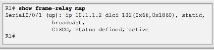
Figure above shows the output of the show frame-relay map command.
Notice that the interface is up and the destination IPv4 address is 10.1.1.2. The DLCI identifies the logical connection being used to reach this interface. This value is displayed in decimal value (102), in hexadecimal value (0x66), and as its value as it would appear on the wire (0x1860).
This is a static entry, not a dynamic entry. The link is using Cisco encapsulation as opposed to IETF encapsulation.
Local Management Interface (LMI, advanced features)
The Frame Relay design provides packet-switched data transfer with minimum end-to-end delays. The original design omits anything that might contribute to delay.
A consortium of Cisco, Digital Equipment Corporation (DEC), Northern Telecom, and StrataCom extended the Frame Relay protocol to provide additional capabilities for complex inter-networking environments. These extensions are referred to collectively as the LMI.
Basically, the LMI is a keep-alive mechanism that provides status information about Frame Relay connections between the router (DTE) and the Frame Relay switch (DCE). Every 10 seconds or so, the end device polls the network, either requesting a dumb sequenced response or channel status information. If the network does not respond with the requested information, the user device may consider the connection to be down. When the network responds with a FULL STATUS response, it includes status information about DLCIs that are allocated to that line. The end device can use this information to determine whether the logical connections are able to pass data.
show frame-relay lmi
The output shows the LMI type used by the Frame Relay interface and the counters for the LMI status exchange sequence, including errors such as LMI timeouts.
It is easy to confuse the LMI and encapsulation.
The LMI is a definition of the messages used between the DTE and the DCE.
Encapsulation defines the headers used by a DTE to communicate information to the DTE at the other end of a VC. The switch and its connected router care about using the same LMI.
- The switch does not care about the encapsulation.
- The endpoint routers (DTEs) do care about the encapsulation.
Optional LMI extensions
Some of the extensions include:
- VC status messages – Provide information about PVC integrity by communicating and synchronizing between devices, periodically reporting the existence of new PVCs and the deletion of already existing PVCs.
VC status messages prevent data from being sent into black holes (PVCs that no longer exist).
- Multicasting – Allows a sender to transmit a single frame that is delivered to multiple recipients. Multicasting supports the efficient delivery of routing protocol messages and address resolution procedures that are typically sent to many destinations simultaneously.
- Global addressing – Provides connection IDs with global rather than local significance, allowing them to be used to identify a specific interface to the Frame Relay network. Global addressing makes the Frame Relay network resemble a LAN in terms of addressing, and ARPs are used as on a LAN.
- Simple flow control – Provides for an XON/XOFF flow control mechanism that applies to the entire Frame Relay interface. It is intended for devices that cannot use the congestion notification bits (i.e., FECN and BECN) that would be leveraged by higher layers, but still require some level of flow control.
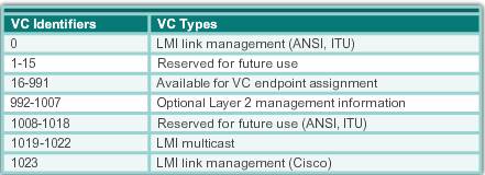
LMI is used to manage Frame Relay links. Each LMI message is classified by a DLCI. The 10-bit DLCI field supports 1,024 VC IDs: 0 to 1,023, as shown in Figure bellow.
The LMI extensions reserve some of these VC IDs, thereby reducing the number of permitted VCs. LMI messages are exchanged between the DTE and DCE using these reserved DLCIs.
There are several LMI types, each of which is incompatible with the others. The LMI type configured on the router must match the type used by the service provider. Three types of LMIs are supported by Cisco routers:
- CISCO – Original LMI extension
- ANSI – Corresponding to the ANSI standard T1.617 Annex D
- Q933A – Corresponding to the ITU standard Q933 Annex A
To display the LMI message information and the associated DLCI numbers, use the command:
show interfaces [type number]
Starting with the Cisco IOS software Release 11.2, the default LMI autosense feature detects the LMI type supported by the directly connected Frame Relay switch. Based on the LMI status messages it receives from the Frame Relay switch, the router automatically configures its interface with the supported LMI type.
If it is necessary to set the LMI type, use the interface configuration command:
R1(config-if)#frame-relay lmi-type [cisco | ansi | q933a]
Configuring the LMI type disables the autosense feature.
In cases where a Frame Relay switch uses non-default timeout settings, the keepalive interval must also be configured on the Frame Relay interface to prevent status exchange messages from timing out. The LMI status exchange messages determine the status of the PVC connection. A large mismatch in the keepalive interval on the router and the switch can cause the switch to declare the router dead. It is important to consult the Frame Relay service provider for information on how to modify the keepalive setting.
By default, the keepalive time interval is 10 seconds on Cisco serial interfaces. You can change the keepalive interval with the interface configuration command:
keepalive time_in_seconds
Status messages help verify the integrity of logical and physical links. This information is critical in a routing environment because routing protocols make decisions based on link integrity.
LMI frame formate
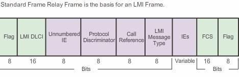 LMI status messages are similar to the Frame Relay frame. In place of the Address field of a Frame Relay frame that is used for data transmission, is an LMI DLCI field.
Following the DLCI field are the Control, Protocol Discriminator, and Call Reference fields. These are the same as with standard Frame Relay data frames. The fourth field indicates the LMI message type and includes one of the three LMI message types supported by Cisco.
Using LMI and invert ARP to map address
LMI status messages combined with Inverse ARP messages allow a router to associate network layer and data link layer addresses.
Let’s use the example as shown above.
when R1 connects to the Frame Relay network, it sends an LMI status inquiry message to the network. The network replies with an LMI status message containing details of every VC configured on the access link.
Periodically, the router repeats the status inquiry, but subsequent responses include only status changes. After a set number of these abbreviated responses, the network sends a full status message.
If the router needs to map VCs to network layer addresses, it sends an Inverse ARP message on each VC. Inverse ARP operates similarly to ARP on an Ethernet local network, with the exception that Inverse ARP does not broadcast requests. With ARP, the sending device knows the Layer 3 IP address and sends a broadcast to learn the destination Layer 2 MAC address. With Inverse ARP, the router knows the Layer 2 address, which is the local DLCI, and sends a request for the destination Layer 3 IP address.
Inverse ARP operation
1, When an interface supporting Inverse ARP becomes active, it initiates the Inverse ARP protocol and formats an Inverse ARP request for the active VC. The Inverse ARP request includes the source hardware, source Layer 3 protocol address, and the known target hardware address. It then fills the target Layer 3 protocol address field with all zeroes. It encapsulates the packet for the specific network and sends it directly to the destination device using the VC.
2, Upon receiving an Inverse ARP request, the destination device will use the address of the source device to create its own DLCI-to-Layer 3 map. It will then send an Inverse ARP response that includes its Layer 3 address information. When the source device receives the Inverse ARP response, it completes the DLCI-to-Layer 3 map using the provided information.
advanced Frame relay concept
- Access rate – Access rate refers to the port speed. The access rate is the rate at which your access circuits join the Frame Relay network. These may be 56 kb/s, T1 (1.544 Mb/s), or Fractional T1 (a multiple of 56 kb/s or 64 kb/s). Access rates are clocked on the Frame Relay switch. It is not possible to send data at higher than the access rate.
- Committed Information Rate (CIR) – Customers negotiate CIRs with service providers for each PVC. The CIR is the amount of data that the network receives from the access circuit. The service provider guarantees that the customer can send data at the CIR. All frames received at or below the CIR are accepted.
The CIR specifies the maximum average data rate that the network undertakes to deliver under normal conditions.
If the customer sends information faster than the CIR on a given DLCI, the network marks some frames with a Discard Eligibility (DE) bit. The network does its best to deliver all packets; however it discards DE packets first if there is congestion.
Note: Many inexpensive Frame Relay services are based on a CIR of zero (0). A CIR of zero means that every frame is a DE frame and the network throws away any frame when it needs to. The DE bit is within the address field of the Frame Relay frame header.
- Oversubscription (more users than the committed, taking advantage of customers):
Service providers sometimes sell more capacity than they have on the assumption that not everyone will demand their entitled capacity all of the time. This over-subscription is analogous to airlines selling more seats than they have in the expectation that some of the booked customers will not show up. Because of over-subscription, there are instances when the sum of CIRs from multiple PVCs to a given location is higher than the port or access channel rate. This can cause congestion and dropped traffic. - Bursting (more speed for the customers, bonus for the customers)
Any network capacity that is being unused is made available or shared with all customers, usually at no extra charge. This allows customers to burst over their CIR as a bonus.Bursting allows devices that temporarily need additional bandwidth to borrow it at no extra cost from other devices not using it. For example, if PVC 102 is transferring a large file, it could use any of the 16 kb/s not being used by PVC 103. A device can burst up to the access rate and still expect the data to get through. The duration of a burst transmission should be less than three or four seconds.
This allows a customer’s traffic to actually “burst” to higher speeds, as available network bandwidth permits. The speed to which data can burst is referred to as the Committed Burst Information Rate (CBIR). For example, a virtual circuit with a CIR of 64 Kbps may have a CBIR of 128 Kbps.
Various terms are used to describe burst rates, including the Committed Burst Size (Bc) and Excess Burst Size (Be).
- The Bc is a negotiated rate above the CIR that the customer can use to transmit for short burst, and represents the maximum allowed traffic under normal working conditions. It allows traffic to burst to higher speeds, as available network bandwidth permits. However, it cannot exceed the access rate of the link. A device can burst up to the Bc and still expect the data to get through. If long bursts persist, then a higher CIR should be purchased.
- The Be describes the bandwidth available above the CIR up to the access rate of the link. Unlike the Bc, it is not negotiated. Frames may be transmitted at this level but are most likely dropped.
CIR < Bursting rate < Access Rate
Example
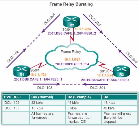
In the example in the figure, the customer is paying for the following:
- An access line with a rate of 64 kb/s connecting their DTE to the DCE of the service provider through serial port S0/0/1.
- Two virtual ports, one at 32 kb/s and the other at 16 kb/s.
- A CIR of 48 kb/s across the entire Frame Relay network. This is usually a flat charge and not connected to the distance.
Figure shows an access rate on serial port S0/0/1 of router R1 to be 64 kb/s. This is higher than the combined CIRs of the two PVCs. Under normal circumstances, the two PVCs should not transmit more than 32 kb/s and 16 kb/s, respectively. As long as the amount of data the two PVCs send does not exceed the CIR, it should get through the network.
Because the physical circuits of the Frame Relay network are shared between subscribers, there are often times where there is excess bandwidth available. Frame Relay can allow customers to dynamically access this extra bandwidth and burst over their CIR for free.
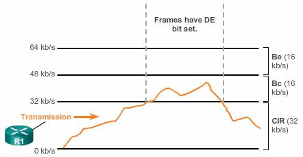
DLCI 102 has a CIR of 32 kb/s with an additional Bc of 16 kb/s for a total of up to 48 kb/s. DLCI 103 has a CIR of 16 kb/s. However, DLCI 103 does not have a Bc negotiated; therefore, the Bc is set to 0 kb/s. Frames within the negotiated CIR are not eligible for discard (DE = 0). Frames above the CIR have the DE bit set to 1, marking it as eligible to be discarded, should the network be congested. Frames submitted in the Bc level are marked as Discard Eligible (DE) in the frame header but will most likely be forwarded.
 Flow control
In periods of congestion, the service provider’s Frame Relay switch applies the following logic rules to each incoming frame based on whether the CIR is exceeded:
- If the incoming frame does not exceed the Bc (committed burst size), the frame is passed.
- If an incoming frame exceeds the Bc, it is marked as DE.
- If an incoming frame exceeds the Bc and the Be(Excess Burst Size), it is discarded.
Frames arriving at a switch are queued or buffered prior to forwarding. As in any queuing system, it is possible that there will be an excessive buildup of frames at a switch. This causes delays, which lead to unnecessary re-transmissions that occur when higher level protocols receive no acknowledgment within a set time. In severe cases, this can cause a serious drop in network throughput. To avoid this problem, Frame Relay incorporates a flow control feature.
To reduce the flow of frames to the queue, the switch notifies DTEs of the problem using the Explicit Congestion Notification bits in the frame address field.
- The FECN bit, indicated by F, is set on every frame that the Frame relay switch receives on the congested link.
- The BECN bit, indicated by B, is set on every frame that the Frame relay switch places onto the congested link.
Note that it is when the Frame relay switch receive or place onto the link.
DTEs receiving frames with the ECN bits set are expected to try to reduce the flow of frames until the congestion clears. If the congestion occurs on an internal trunk, DTEs may receive notification even though they are not the cause of the congestion.