Basic of VPN knowledge can be found here: http://frankfu.click/networking/networking-fundamental/secure-site-to-site-connection-vpnipsecgre/
Complex VPN
Site-to-site VPN topologies continue to evolve. Examples of more complex VPN topologies include Multiprotocol Label Switching (MPLS) VPN, Dynamic Multipoint VPN (DMVPN) and Group Encrypted Transport VPN (GETVPN).
DMVPN
An MPLS VPN consists of a set of sites that are interconnected by means of an MPLS provider core network. At each customer site, one or more customer edge (CE) devices attach to one or more provider edge (PE) devices. MPLS VPNs are easier to manage and expand than conventional VPNs. When a new site is added to an MPLS VPN, only the service provider’s edge device that provides services to the customer site needs to be updated.
A DMVPN enables the auto-provisioning of site-to-site IPsec VPNs, combining three Cisco IOS software features: Next Hop Resolution Protocol (NHRP), multipoint Generic Routing Encapsulation (GRE), and IPsec VPN. This combination eases the provisioning challenges for customers, and provides secure connectivity between all locations.
For more, check here: http://frankfu.click/networking/cisco/ccnp/dynamic-multi-point-vpn-dmvpn-ccnp/
GETVPN
GETVPN uses a trusted group to eliminate point-to-point tunnels and their associated overlay routing. All group members (GMs) share a common security association (SA), also known as a group SA. This enables GMs to decrypt traffic that was encrypted by any other GM. In GET VPN networks, there is no need to negotiate point-to-point IPsec tunnels between the members of a group, because GET VPN is “tunnel-less.”
Hairpinning can also be used when remote-access VPNs must connect to the VPN terminating device at corporate headquarters before traffic is permitted to go to the Internet.
VPN technologies
Hairpinning is a term used to describe a situation in which VPN traffic that enters an interface may also be routed out of that same interface.
Split tunneling can be used if the corporate policy dictates that VPN traffic must be split between traffic destined for the corporate subnets (trusted) and traffic destined to the Internet (untrusted).
IPsec protocols
The two main IPsec protocols are Authentication Header (AH) and Encapsulation Security Protocol (ESP). The IPsec protocol is the first building block of the framework. The choice of AH or ESP establishes which other building blocks are available.
Authentication Header
AH achieves authenticity by applying a keyed one-way hash function to the packet to create a hash or message digest. The hash is combined with the text and is transmitted in plaintext. The receiver detects changes in any part of the packet that occur during transit by performing the same one-way hash function on the received packet and comparing the result to the value of the message digest that the sender supplied. Authenticity is assured because the one-way hash also employs a shared secret key between the two systems.
The AH function is applied to the entire packet, except for any IP header fields that normally change in transit. Fields that normally change during transit are called mutable fields. For example, the Time to Live (TTL) field is considered mutable because routers modify this field.
The AH process occurs in this order:
1. The IP header and data payload are hashed using the shared secret key.
2. The hash builds a new AH header, which is inserted into the original packet.
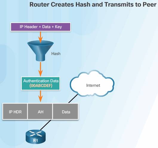
3. The new packet is transmitted to the IPsec peer router.
4. The peer router hashes the IP header and data payload using the shared secret key, extracts the transmitted hash from the AH header, and compares the two hashes.
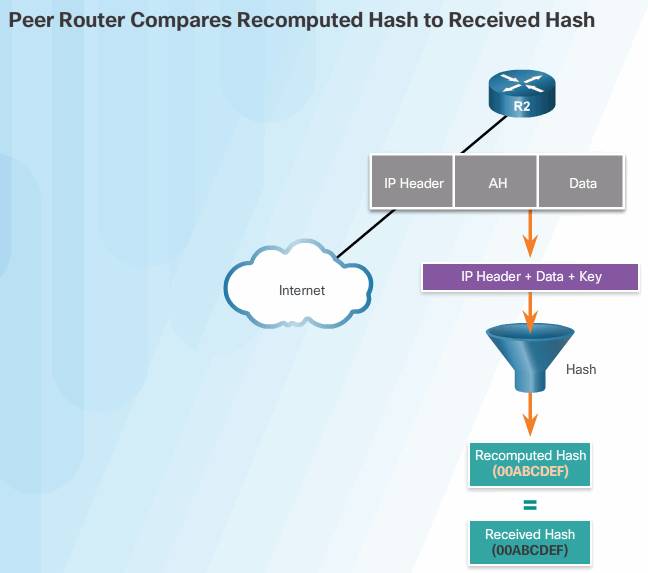
The hashes must match exactly. If one bit is changed in the transmitted packet, the hash output on the received packet changes and the AH header will not match.
AH supports MD5 and SHA algorithms.
Advantage:
- AH provide the IP header integrity check (ESP does not).
Disadvantage:
- AH does not provide encryption, Anti-replay machanism.
- AH may not work if the environment uses NAT,because of integrity check.
ESP
ESP provides confidentiality by encrypting the payload. It supports a variety of symmetric encryption algorithms. If ESP is selected as the IPsec protocol, an encryption algorithm must also be selected. It does not have a port number, but has a set of parameters.
The default algorithm for IPsec is 56-bit DES. Cisco products also support the use of 3DES, AES, and SEAL for stronger encryption.
ESP can also provide integrity and authentication. First, the payload is encrypted. Next, the encrypted payload is sent through a hash algorithm, such as MD5 or SHA. The hash provides authentication and data integrity for the data payload.
Optionally, ESP can also enforce anti-replay protection. Anti-replay protection verifies that each packet is unique and is not duplicated. This protection ensures that a hacker cannot intercept packets and insert changed packets into the data stream. Anti-replay works by keeping track of packet sequence numbers and using a sliding window on the destination end.
When a connection is established between a source and destination, their counters are initialized at zero. Each time a packet is sent, a sequence number is appended to the packet by the source. The destination uses the sliding window to determine which sequence numbers are expected. The destination verifies that the sequence number of the packet is not duplicated and is received in the correct order.
For example, if the sliding window on the destination is set to one, the destination is expecting to receive the packet with the sequence number one. After it is received, the sliding window moves to two. When detection of a replayed packet occurs, such as the destination receiving a second packet with the sequence number of one, an error message is sent, the replayed packet is discarded, and the event is logged.
Anti-replay is typically used in ESP, but it is also supported in AH.
ESP Encrypts and Authenticates
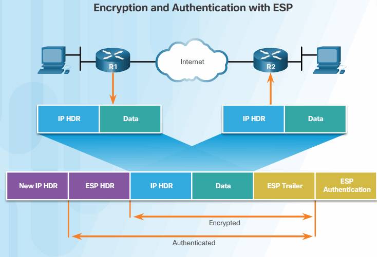
ESP provides the ability to protect the original data because the entire original IP datagram and ESP trailer are encrypted. With ESP authentication, the encrypted IP datagram and trailer, and the ESP header are included in the hashing process, as shown in the figure. Then, a new IP header is attached to the authenticated payload. The new IP address is used to route the packet through the Internet.
When both authentication and encryption are selected, encryption is performed first. One reason for this order of processing is that it facilitates rapid detection and rejection of replayed or bogus packets by the receiving device. Prior to decrypting the packet, the receiver can authenticate inbound packets. By doing this, it can quickly detect problems and potentially reduce the impact of DoS attacks. To reiterate, ESP provides confidentiality with encryption and provides integrity with authentication.
Up to this point, the discussion of IPsec has focused on IPv4. However, IPsec was initially established to provide security for IPv6 packets. Therefore, the IPsec implementations for IPv4 and IPv6 are similar as far as the standards are concerned. In IPv4, AH and ESP are IP protocol headers. IPv6 uses the extension headers with a next-header value of 50 for ESP and 51 for AH.
Transport and Tunnel Modes
ESP and AH can be applied to IP packets in two different modes, transport mode and tunnel mode, as shown in Figure below.
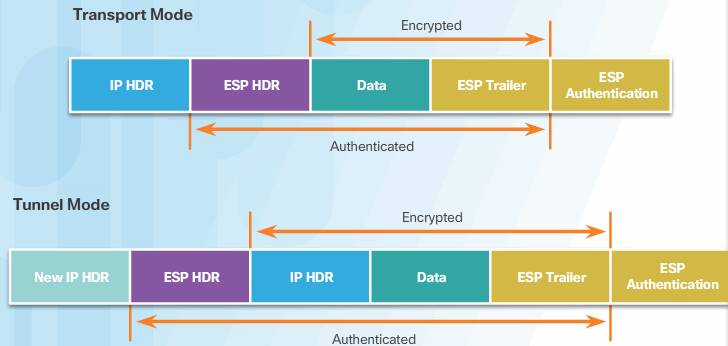
Transport Mode
In transport mode, security is provided only for the transport layer of the OSI model and above. Transport mode protects the payload of the packet but leaves the original IP address in plaintext. The original IP address is used to route the packet through the Internet. ESP transport mode is used between hosts.
Tunnel Mode
Tunnel mode provides security for the complete original IP packet. The original IP packet is encrypted and then it is encapsulated in another IP packet. This is known as IP-in-IP encryption. The IP address on the outside IP packet is used to route the packet through the Internet.
ESP tunnel mode is used between a host and a security gateway, or between two security gateways. For host-to-gateway applications, a home office might not have a router to perform the IPsec encapsulation and encryption. In this case, an IPsec client running on the PC performs the IPsec IP-in-IP encapsulation and encryption. For gateway-to-gateway applications, rather than load IPsec on all of the computers at the remote and corporate offices, it is easier to have the security gateways perform the IP-in-IP encryption and encapsulation. At the corporate office, the router de-encapsulates and decrypts the packet.
AH transport mode provides authentication and integrity for the entire packet. It does not encrypt the data, but it is protected from modification. AH tunnel mode encapsulates the IP packet with an AH and a new IP header, and signs the entire packet for integrity and authentication.
IKE protocol
The Internet Key Exchange (IKE) protocol is a key management protocol standard. IKE is used in conjunction with the IPsec standard. IKE automatically negotiates IPsec security associations and enables IPsec secure communications. IKE enhances IPsec by adding features and simplifies configuration for the IPsec standard. Without IKE in place, IPsec configuration would be a complex, manual configuration process that would not scale well.
IKE is a hybrid protocol that implements key exchange protocols inside the Internet Security Association Key Management Protocol (ISAKMP) framework. ISAKMP (pronounced “Ice-a-camp”) defines the message format, the mechanics of a key exchange protocol, and the negotiation process to build an SA for IPsec. IKE implements portions of the Oakley and SKEME protocols but is in no way dependent on these protocols. For example, some of the IKE exchange process is based on the Oakley protocol and the public key encryption method used by IKE is based on SKEME. Further discussion of Oakley and SKEME are beyond the scope of this course.
Instead of transmitting keys directly across a network, IKE calculates shared keys based on the exchange of a series of data packets. This disables a third party from decrypting the keys even if the third party captured all of the exchanged data that was used to calculate the keys. IKE uses UDP port 500 to exchange IKE information between the security gateways. UDP port 500 packets must be permitted on any IP interface that is connecting a security gateway peer.
Phase 1 and 2 Key Negotiation
IKE uses ISAKMP for phase 1 and phase 2 of key negotiation. In phase 1 and phase 2, two sessions are created, phase 1 is the management session, phase 2 is the security association.
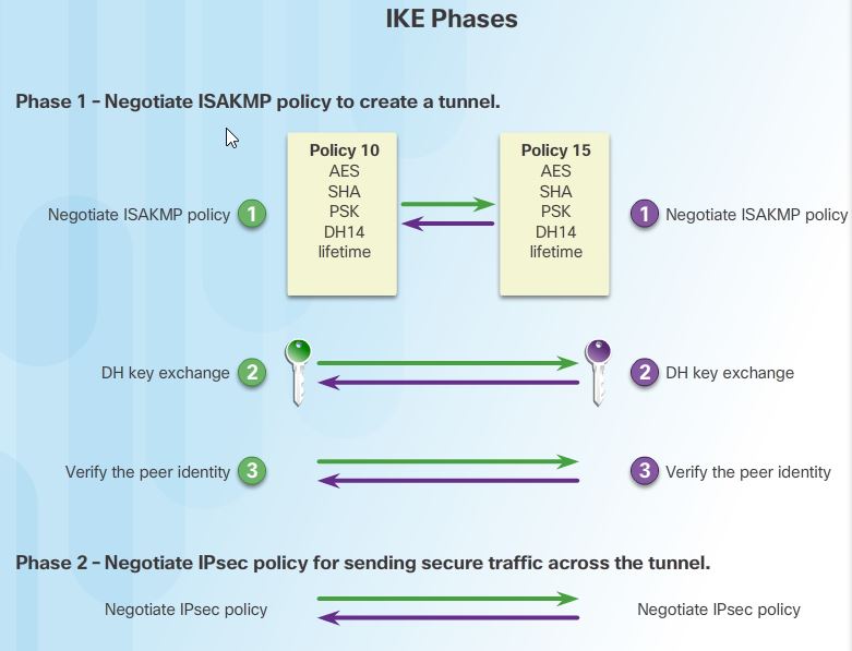
Phase 1 (Bidirectional)
Phase 1 negotiates a security association (a key) between two IKE peers. The key negotiated in phase 1 enables IKE peers to communicate securely in phase 2. During phase 2 negotiation, IKE establishes keys (security associations) for other applications, such as IPsec.
In Phase 1, two IPsec peers perform the initial negotiation of SAs. The basic purpose of Phase 1 is to negotiate ISAKMP policy, authenticate the peers, and set up a secure tunnel between the peers. This tunnel will then be used in Phase 2 to negotiate the IPsec policy.
Note: The phrases IKE policy and ISAKMP policy are equivalent. The phrase ISAKMP policy is used in this course to better match the commands (crypto isakmp policy, show isakmp policy, etc.) as well as to clarify that the ISAKMP policy applies to the IKE Phase 1 tunnel.
Phase 1 can be implemented in main mode or aggressive mode. When main mode is used, the identities of the two IKE peers are hidden. Aggressive mode takes less time than main mode to negotiate keys between peers. However, since the authentication hash is sent unencrypted before the tunnel is established, aggressive mode is vulnerable to brute-force attacks.
Note: In Cisco IOS software, the default action for IKE authentication is to initiate main mode. However, Cisco IOS software will respond in aggressive mode to an IKE peer that initiates aggressive mode.
Phase 2(unidirection)
The purpose of IKE Phase 2 is to negotiate the IPsec security parameters that will be used to secure the IPsec tunnel, as shown in the figure. IKE Phase 2 is called quick mode and can only occur after IKE has established a secure tunnel in Phase 1. SAs are negotiated by the IKE process ISAKMP on behalf of IPsec, which needs encryption keys for operation. Quick mode negotiates the IKE Phase 2 SAs. In this phase, the SAs that IPsec uses are unidirectional; therefore, a separate key exchange is required for each data flow.
Quick mode also renegotiates a new IPsec SA when the IPsec SA lifetime expires. Basically, quick mode refreshes the keying material that creates the shared secret key. This is based on the keying material that is derived from the DH exchange in Phase 1.
IKE version 2, a next-generation key management protocol based on RFC 4306, is an enhancement of the IKE protocol. IKE version 2 supports NAT detection during Phase 1 and NAT Traversal (NAT-T) during Phase 1. If both VPN devices are NAT-T capable, and if they detect that they are connecting to each other through a NAT device, NAT-T is auto detected and auto negotiated. NAT-T encapsulates ESP packets inside UDP and assigns both the Source and Destination ports as 4500. Now ESP packets can traverse NAT. Click here to learn more about NAT-T.
Related tutorial: